![]()
This new and improved module enables you to import and utilize data from other systems more effectively. The toolset has been expanded to provide more ways to find and heal problems that prevent a model from solidifying.
|
|
This new and improved module enables you to import and utilize data from other systems more effectively. The toolset has been expanded to provide more ways to find and heal problems that prevent a model from solidifying. |
This tutorial will use the tools in the New Import DataDoctor to repair a STEP file that has gaps, holes, and extra surfaces.
1. Set Working Directory to IDD
2. Open ![]() and set the Type to All Files (*) and double-click the idd_tutorial.stp file.
and set the Type to All Files (*) and double-click the idd_tutorial.stp file.
3. Select OK button from the Import New Model. Close the information window that appears.
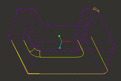
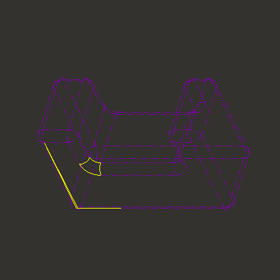
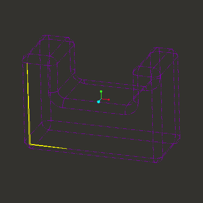
4. Ensure that the model is being shown in Wireframe ![]() .
.
|
|
Notice that there are multiple edges that are yellow vs. purple. This denotes one-sided edges and they need to be repaired to make this part a solid. |
5. RMB CLICK on the Import Feature from the Model Tree and select Edit Definition.
6. Select the Import DataDoctor ... ![]() icon in the right-hand toolbar.
icon in the right-hand toolbar.
There are 3 modes available:
|
Repair Mode |
In Repair mode, you can remove gaps and sliver surfaces, add uv-curves, and fix tangency in the imported geometry. | |
|---|---|---|
|
|
Modify Mode |
In Modify mode, you can modify individual curves and surfaces, replace one-sided edges with a uv-curve, and change surface math properties using tools and procedures such as merge, intersect, and so on. |
|
|
Featurize Mode |
Featurize mode is the default mode when you import a model into Pro/ENGINEER. In this mode, you can convert individual surfaces or group of surfaces and quilts to analytical, spline, or procedural surfaces or quilts. You can also use surface conversion tools such as convert to plane, convert to cylinder, and so on to convert surfaces. |
The tools on the IDD Display Toolbar are the commonly used tools in IDD.
|
|
Repair Mode |
|---|---|
|
|
Modify Mode |
|
|
Featurize Mode |
|
|
Display Tangency |
|
|
Display Frozen |
|
|
Display Vertices |
|
|
Display Wireframe |
7. Note the new Model Tree tab - it is the GTS Tree (Geometry and Topology Structure) and is similar to the standard Pro/ENGINEER Model Tree except it shows the Topology of the geometry you are attempting to repair.
8. Click  from the Model tree > Expand All or > Collapse All to expand or collapse all branches respectively.
|
|
The ID numbers for your imported model may be different. |
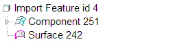
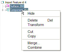
9. On the GTS Tree, RMB on Component 251 and click Hide. Component 251 and its surfaces are temporarily hidden in the graphics window.
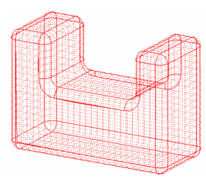
10. Select Component 251 on the GTS Tree. The model appears in the graphics window as a red mesh. Surfaces that appear as a red mesh as shown in the following figure indicate that they are hidden.
11. Select Surface 242 on the GTS Tree. Notice that it is and extra surface that does not belong to Component 251.
12. On the GTS Tree, right-click Surface 242 and click Delete on the shortcut menu.
13. On the GTS Tree, RMB on Component 251 and click UnHide.
In the previous section, you learned some basic operations such as Hide, UnHide, and Delete that you can perform using the GTS Tree. You will now select the gaps present in the model using the Search Tool. You can define the gaps only in the Repair mode. Searching allows you to find and select gaps in your model without selecting them in the graphics window. You can specify rules for the search operation using attributes such as size value.
1. Click ![]() on the IDD Display Menu.
on the IDD Display Menu.
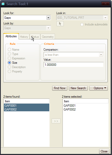
2. Click Find ![]() on the Edit toolbar to open the Search Tool.
on the Edit toolbar to open the Search Tool.
3. Under Look for, select Gaps.
4. Click Find Now with Value set to the default of 0.099129. A list of found items and an area to transfer selected items are displayed. No items are found because the model does not contain gaps with the specified value.
5. Set Value to 1 and click Find Now. GAP0001 and GAP0002 appear in the list of found items. The gaps that appear in the list of found items have a value of 1.
6. Select these two items and click to ![]() transfer them to the selected items area. Close the Search Tool.
transfer them to the selected items area. Close the Search Tool.
You will now close the gaps that you have found using the Search Tool. Before closing the gaps you must add the edges (gaps that you have found using the Search Tool) to wireframe. When you add edges to the wireframe, Pro/ENGINEER automatically creates a wireframe piece that forms two closed loops and closes the gap.
In this section you will define the gaps in the model by selecting them in the graphics window.
1. Click Define Gap![]() (IDD > Define Gap) on the IDD Repair Tools toolbar. GAP0001 is displayed on the left hand side of the dialog box.
(IDD > Define Gap) on the IDD Repair Tools toolbar. GAP0001 is displayed on the left hand side of the dialog box.
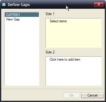
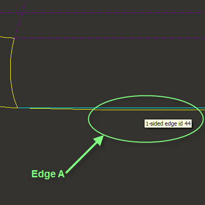
2. Click the Side 1 collector box in the Define Gaps dialog box and select Edge A (1-sided edge id 44) in the graphics window as shown in the following figure.
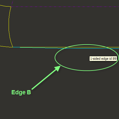
3. Click the Side 2 collector box in the Define Gaps dialog box and select Edge B (1-sided edge id 89) in the graphics window as shown in the following figure.
4. Click OK button from the dialog box.
Now that you have defined the gaps to be closed, you must add the edges to the wireframe to enable Pro/ENGINEER to close the gaps.
5. Click Add to WireFrame ![]() on the IDD Repair Tools toolbar to add the edges to the wireframe.
on the IDD Repair Tools toolbar to add the edges to the wireframe.
6. Click Repair ![]() on the IDD Repair Tools toolbar. The repair dashboard appears. The new surfaces that will be created are highlighted in the graphics window.
on the IDD Repair Tools toolbar. The repair dashboard appears. The new surfaces that will be created are highlighted in the graphics window.
7. Click ![]() on the repair dashboard to close the gaps. This is what the model should look like now.
on the repair dashboard to close the gaps. This is what the model should look like now.
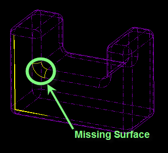
After closing the small gaps you will close the missing surface as shown in the following figure, using the boundary blend tool. With the boundary blend tool, you can create a boundary blended feature between reference entities that defines the surface in one or two directions. The first and last entities selected in each direction define the surface boundary.
1. Click Featurize ![]() on the IDD Display toolbar to change the IDD mode.
on the IDD Display toolbar to change the IDD mode.
You can add boundary blend surfaces only in the Featurize mode.
![]()
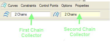
2. Click Boundary Blend ![]() on the IDD Featurize Tools toolbar (IDD > Boundary Blend Surface). The boundary blend dashboard appears and the first direction chain collector is active.
on the IDD Featurize Tools toolbar (IDD > Boundary Blend Surface). The boundary blend dashboard appears and the first direction chain collector is active.
3. Select curves A and B for the first direction of the surface, as shown in the following figure. Once you select curve A, hold down CTRL and select curve B.
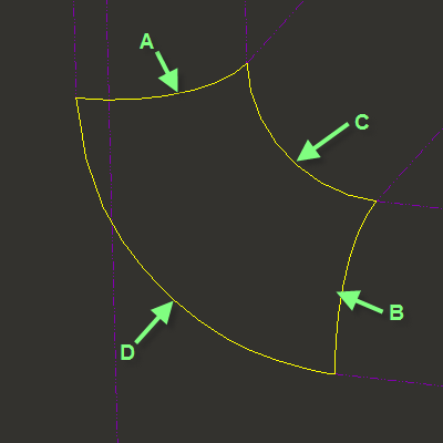
4. Click second direction chain collector on the boundary blend dashboard and select curves C and D in the graphics window as shown in the previous figure.
5. Click ![]() on the boundary blend dashboard to create the boundary blend surface.
on the boundary blend dashboard to create the boundary blend surface.
Now that you have created a boundary blend surface, you must combine the newly created boundary blend surface with other surfaces in the imported model. When you combine the boundary blend surface with other surfaces, Pro/ENGINEER creates a combine node.
1. In the Model Tree, select the nodes as shown.
2. Click RMB > Combine.
This is what the model should look like now.
At this point you will finish repairing the model by moving a vertex using the Modify Mode.
1. Click Modify Mode ![]() on the IDD Display toolbar to change the IDD mode.
on the IDD Display toolbar to change the IDD mode.
2. Click Move Vertex![]() on the Modify Mode Toolbar.
on the Modify Mode Toolbar.
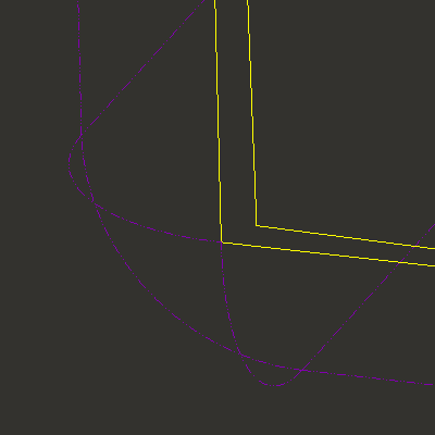
3. Select the vertex with the LMB and hold to drag the vertex to the correct corner. Zoom in as close as possible to get a good fit.
![]()
4. Notice that it automatically zips the gaps. If there are still open edges (i.e., magenta) then zoom in and repeat the above steps.
5. Click ![]() on the IDD Featurize Tools toolbar.
on the IDD Featurize Tools toolbar.
The model is fully repaired at this point. The next steps will convert the quilt to a solid feature..
1. Click Edit > Feature Properties. The Properties dialog box opens.
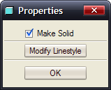
2. Click Make Solid to convert the closed volume into a solid.
3. Click OK button in the Properties dialog box.
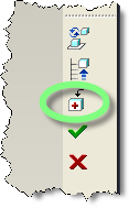
4. Click ![]() to exit the Edit Definition Mode.
to exit the Edit Definition Mode.