|
|
|
Tutorial Summary
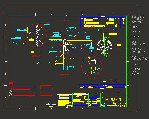
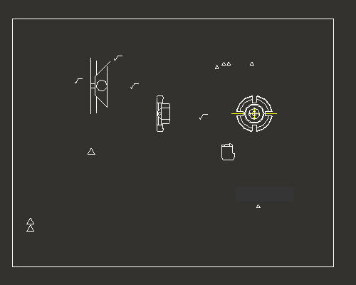
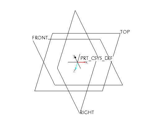
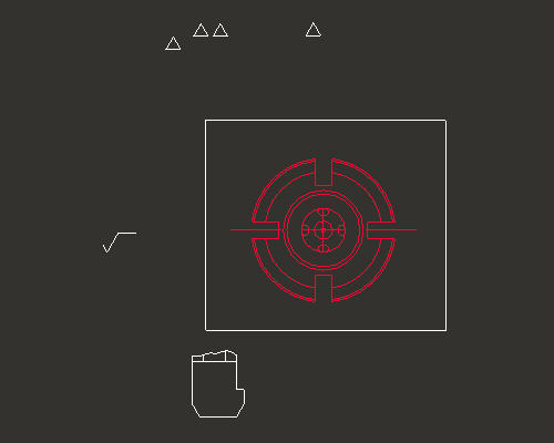
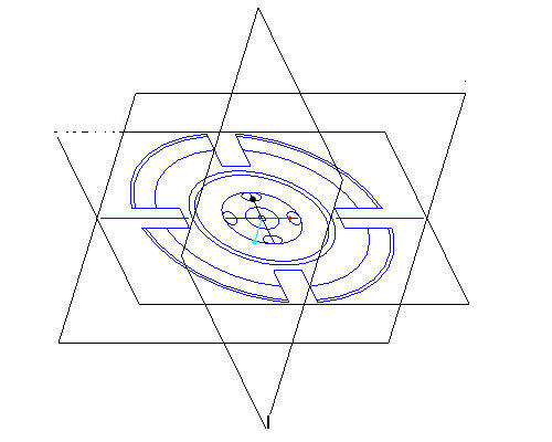
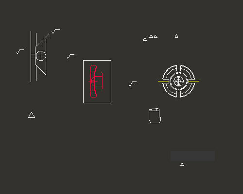
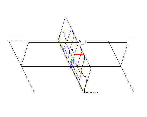
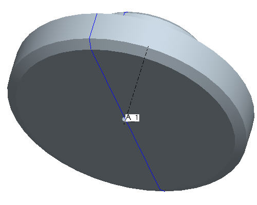
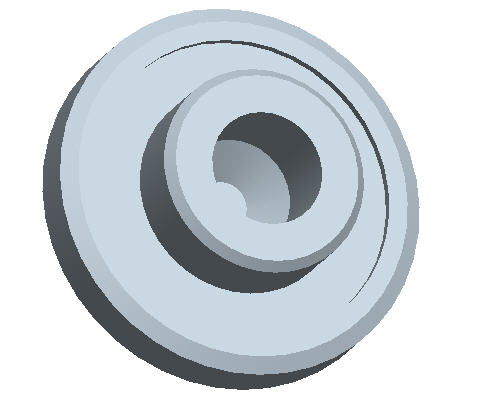
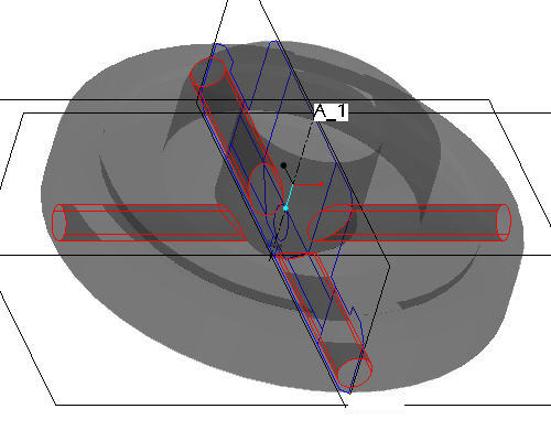
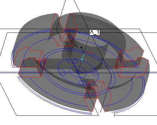
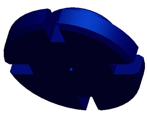
This tutorial opens a non-native drawing file in Pro\ENGINEER and uses sketches from the drawing views to create solid geometry. Step 1: Launch Pro/ENGINEER and import the AutoCad DWG file Step 2: Use layers to blank the extraneous drawing entities Step 5: Use the side view from the drawing as the side sketch of the part Step 6: Create the first solid feature as a revolve of the side sketch Step 7: Change the part color to transparent Step 8: Add radial holes Step 9: Create the slot cuts Step 10: Change the appearance of the model As an alternative to having this open along-side Pro/Engineer, you can also view a printable version by clicking here. To download a finished model for Tryout version, click here. |
|
|
|