Task 3. Assemble the belt drive pulley for the output of the transmission
-
Select Component Assemble
 icon in the right side toolbar.
 -
From the Open dialog box, select BELT_DRIVE.PRT as the part to assemble and select Open. The belt drive model will appear in the graphics window in yellow to represent the part being assembled.
-
Left click on the outside surface of the output shaft of the transmission as shown in the figure below. Notice the surface selected is in red with the "automatic" note pointing to the surface.
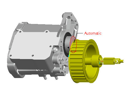

To select a surface, move the cursor over the surface until it turns blue. Then select the surface using the left mouse button.
-
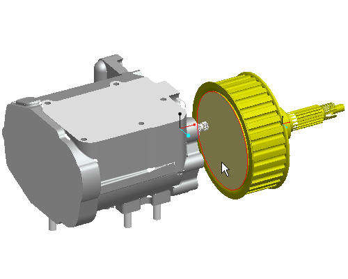
MIDDLE-DRAG in the window to spin the model to an orientation similar to the figure below.

Middle-drag implies a middle mouse button "press and hold", while moving the mouse.
-
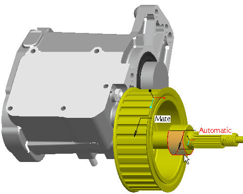
Left click on the surface on the belt drive part as shown in the figure below.
The Automatic constraint will automatically select the appropriate constraint type based on the references selected on the component and the assembly.
-
Notice that the belt drive part is mated with the output shaft of the transmission however the component is not fully constrained.
-
Select CTRL + D to reorient the model into the default orientation.
-
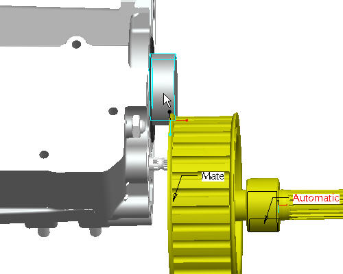
Select the cylindrical surface on the drive pulley as shown in the figure below.
-
Orient the model to better select the cylindrical surface of the output shaft on the transmission case. Roll the scroll button toward you to zoom in. Use SHIFT + MIDDLE-DRAG to pan the model to the center of the screen. Use MIDDLE-DRAG to rotate the model.
-
Select the cylindrical surface of the output shaft from the transmission case as shown in cyan in the figure below. Notice how the automatic constraint aligns the two shafts together.
-
Select Complete Component
 in the dashboard.
Select the Placement tab in the dashboard to review or reselect an existing constraint type and the references on the component or the assembly.
-
Select Repaint
 icon from the main toolbar.
 -
Select CTRL+D to reorient the model into the default orientation.
|
|
The belt drive pulley will be assembled by aligning the pulley shaft to the output shaft of the transmission and mating two surfaces. Only two degrees of freedom are defined for the component to be FULLY CONSTRAINED since the pulley shaft and the output shaft are free to rotate. |