This tutorial is intended to be used alongside Pro/ENGINEER Wildfire 3.0 Tryout Edition and Pro/ENGINEER Wildfire 3.0 Commercial Edition.
Please make sure that Pro/ENGINEER Wildfire 3.0 Tryout (Commercial) Edition is installed on your machine before continuing. For Tryout Edition, files used or created during this tutorial cannot be used with commercial version of Pro/ENGINEER.
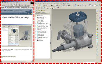
Your web browser and Pro/ENGINEER can be resized and laid out as shown below to facilitate your experience.
 Positioning Tutorial Window |
It is recommended that you maximize the amount of working area on your screen by setting your monitor to the highest resolution setting, for example 1600x1200.
Use the Commands at the top of the page to navigate through the tutorial. Click Next to proceed to the next slide and Previous to return to the previous slide. Click Home to return to the beginning of the tutorial. If the page contains more information than the visible screen, a scroll bar will appear along the vertical side. Scroll through the entire contents before progressing to the next step.
You will see various icons throughout the tutorial:
There are several conventions used in this tutorial:
Step 1: Develop a protrusion from a 2D Sketch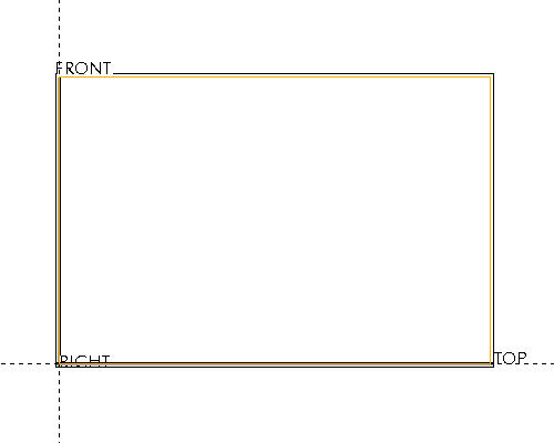
Step 2: Generate additional features such as a protrusion, hole, and rounds to develop the model
Step 3: Hollow the part geometry
Step 4: Explore different design solutions by modifying the model geometry
As an alternative to having this open along-side Pro/Engineer, you can also view a printable version by clicking here.
|
Task 1. Generate a protrusion from a 2D sketch |
Start Pro/ENGINEER Wildfire 3.0 Tryout Edition if necessary.
If Pro/ENGINEER is already running ensure all windows are closed, and all items from the previous exercise are erased from memory.
In the Navigator Folder Browser ![]() , browse to the following folder C:\HANDS-ON_WF3\PART_MODELING_TUTORIAL
, browse to the following folder C:\HANDS-ON_WF3\PART_MODELING_TUTORIAL
Right-click the PART_MODELING_TUTORIAL folder and select Set Working Directory.
Select the New ![]() icon on the main toolbar at the top left of the screen. The New object dialog opens.
icon on the main toolbar at the top left of the screen. The New object dialog opens.
Accept the default settings in this dialog and select OK. Default templates are used when a new part or assembly is created. The default template are an initial design model that contains default features, layers, views, parameters and units.
![]()
Select the Sketch Tool ![]() icon on the right toolbar to create a sketch.
icon on the right toolbar to create a sketch.
|
|
The Sketch Tool allows the user to define a shape using 2-D entities that can be used later to create a sketched feature |
The Sketch dialog opens, and in the message area located at the bottom left of the screen, you are prompted to Select a plane or surface to define sketch plane.
Select the datum plane named TOP as the sketch plane, then select Sketch from the Sketch dialog in the upper right corner of the screen. This opens the sketch tool.
Select the Create Rectangle ![]() tool from the sketch toolbar on the right of the screen.
tool from the sketch toolbar on the right of the screen.
Left select once at that center of the intersecting datum planes to begin sketching a rectangle. Move the cursor diagonally up and right and then left select once again to complete the rectangle as shown below.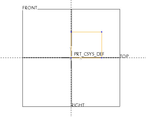
Select the Select Item ![]() tool.
tool.
|
|
The system automatically creates default dimensions to define the shape. These "weak" dimensions can be strengthen to establish design intent so that the model can be modified with predictable results. |
Double click the horizontal dimension and modify the value to 30.
Double click the vertical dimension and modify the value to 20.
Select the Sketch Complete ![]() icon to complete the sketch.
icon to complete the sketch.
Press CTRL+D on the keyboard to return to the default orientation of the model.
With the sketch still highlighted, select the Extrude ![]() tool to begin extruding the sketch that was just completed.
tool to begin extruding the sketch that was just completed.
|
|
An extruded feature is a sketched feature that extrudes a sketch perpendicular to a sketching plane to create a protrusion, cut or surface. |
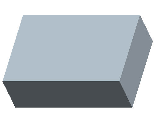
Double click the extruded depth value on the screen and modify it to 10.
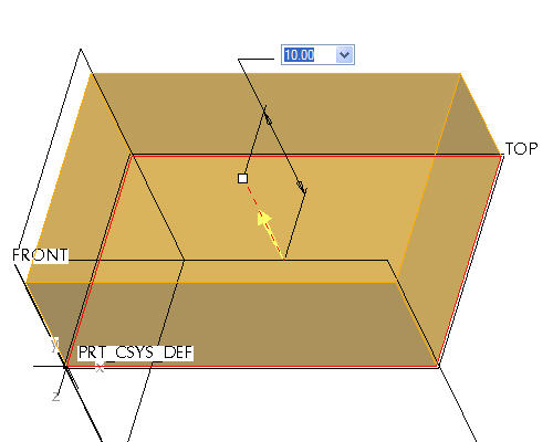
Select Complete Feature ![]() from the dashboard in the lower right hand corner of the screen.
from the dashboard in the lower right hand corner of the screen.
|
Task 2. Create additional features |
Select the Hole ![]() tool from the right toolbar.
tool from the right toolbar.
|
|
Direct features, such as holes and rounds, enable quick placement of features on the model without requiring a predefined shape. |
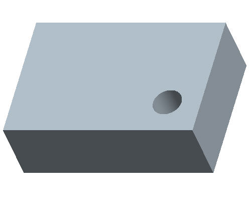
Select on the top surface of the part, near the location shown in the following figure.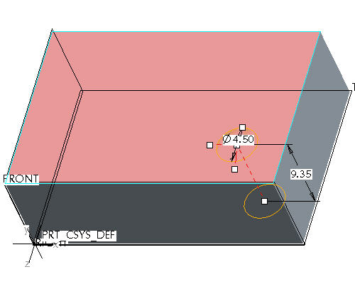
Select and Hold with Left Mouse Button to drag the location handles to the surfaces shown below.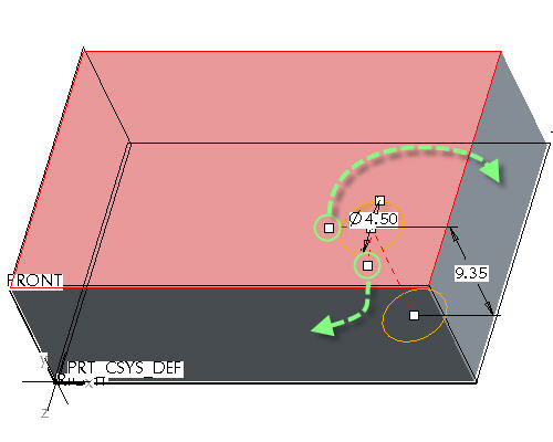
|
|
This will create dimensions defining the location of the hole on the surface. |
Double click the depth dimension and modify the value to 7.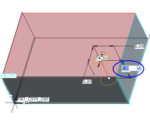
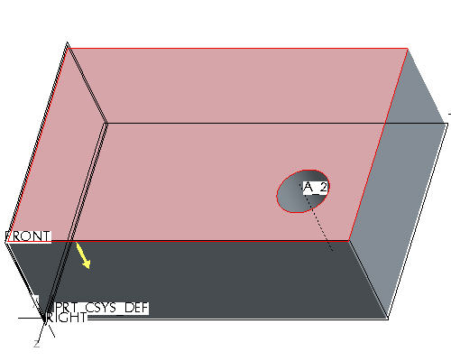
Select Complete Feature ![]() from the dashboard in the lower right hand corner of the screen.
from the dashboard in the lower right hand corner of the screen.
Press CTRL+D on the keyboard to return to the default orientation of the model.
Select the Sketch Tool ![]() icon on the right toolbar to create a sketch.
icon on the right toolbar to create a sketch.
The Sketch dialog opens, and in the message area located at the bottom left of the screen, you are prompted to Select a plane or surface to define sketch plane.
Select anywhere on the top surface of the model shown in the figure below, to select the sketch plane.
Select Sketch from the Sketch dialog in the upper right corner of the screen.
This brings you into the sketch tool.
Select the Create Rectangle ![]() tool from the sketch toolbar on the right of the screen.
tool from the sketch toolbar on the right of the screen.
Create a rectangular sketch and using the Select Item ![]() tool.
tool.
Double click on the parameter values to modify the dimensions as shown below.
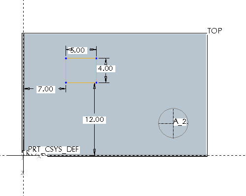
Select the Sketch Complete ![]() icon to complete the sketch.
icon to complete the sketch.
Press CTRL+D on the keyboard to return to the default orientation of the model.
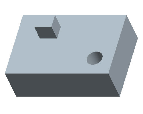
Select the Extrude ![]() tool to begin extruding the sketch that was just completed.
tool to begin extruding the sketch that was just completed.
Double click the extruded depth value shown below on the screen, and modify it to 5.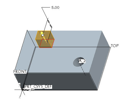
Select Complete Feature ![]() from the dashboard in the lower right hand corner of the screen.
from the dashboard in the lower right hand corner of the screen.
Select Datum Planes ![]() , Datum Points
, Datum Points ![]() , Datum Axes
, Datum Axes ![]() , and Coordinate Systems
, and Coordinate Systems ![]() in the main toolbar to disable their display.
in the main toolbar to disable their display.
|
|
These buttons toggle datum planes, axes, points and coordinate systems on and off so that your graphics window doesn't become too cluttered. |
|
Task 3. Create Rounds |
Start the Round Tool ![]() from the right toolbar.
from the right toolbar.
|
|
Rounds add or remove material by creating smooth transitions between existing geometry. Pro/ENGINEER awaits the selection of edges and/or surfaces to determine round locations. |
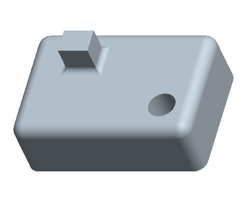
Press and hold CTRL on the keyboard and select the four vertical edges on the model as shown below.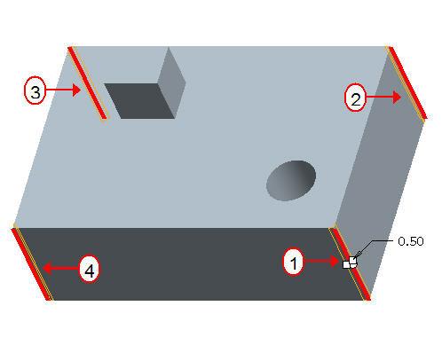
Double click the radius dimension and modify its value to 2.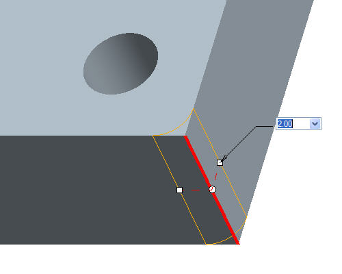
Click Complete Feature ![]() from the dashboard in the lower right hand corner of the screen.
from the dashboard in the lower right hand corner of the screen.
Start the Round Tool ![]() from the right toolbar again.
from the right toolbar again.
Select the top edge as shown below.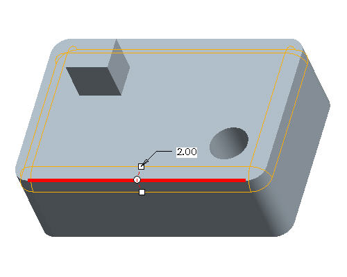
|
|
The surfaces bordering the edge reference form the rolling tangent attachment for the round. The round propagates across tangent neighbor edges unit it encounters a break tangency. |
Click Complete Feature ![]() from the dashboard in the lower right hand corner of the screen.
from the dashboard in the lower right hand corner of the screen.
Start the Round Tool ![]() from the right toolbar again.
from the right toolbar again.
Cursor over the edge at the base of the 2nd extrude feature and while it is highlighted, click the right click once. See the location of the cursor shown below.
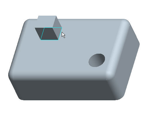
While the loop of edges around the base of that feature are highlighted, click once with the left click to select them, as shown below.
Double click the radius value and modify it to 1.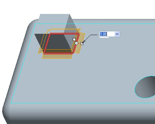
|
|
Aside from single or tangent edges, the user can select an "Intent chain" which enables the round to select the references by the feature rather than by specific entities. |
Click Complete Feature ![]() from the dashboard in the lower right hand corner of the screen.
from the dashboard in the lower right hand corner of the screen.
|
Task 4. Hollow the part |
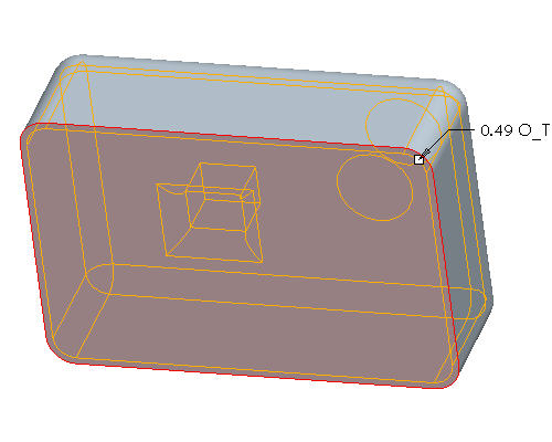
Press MIDDLE-DRAG to rotate the model so the bottom surface is visible as shown below.
|
|
Middle-drag implies a middle mouse button "press and hold", while moving the mouse. |
Start the Shell Tool ![]() from the toolbar on the right of the screen.
from the toolbar on the right of the screen.
|
|
Shell features remove surfaces to hollow out a design model, leaving walls with specified thickness values. |
Select anywhere on the bottom surface of the part. The model will appear as shown below.
Click Complete Feature ![]() from the dashboard in the lower right hand corner of the screen.
from the dashboard in the lower right hand corner of the screen.
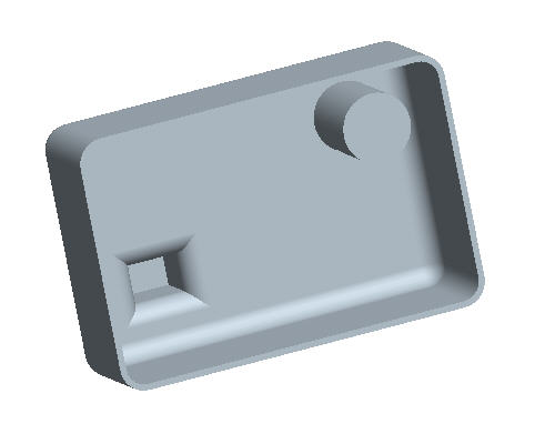
This will hollow the part as shown below.
|
Task 5. Explore design options |
Press CTRL + D on the keyboard to return to the default orientation of the model.
Right click on SKETCH 2 from the model tree on the left side of the screen and select Edit Definition.
With the Select Item ![]() tool selected hold the left mouse button and drag a window to box select the rectangular sketch shown below.
tool selected hold the left mouse button and drag a window to box select the rectangular sketch shown below. 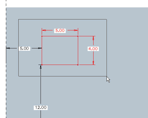
Press DELETE on the keyboard.
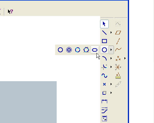
Using the down arrow next to the circle tool![]() select the ellipse tool
select the ellipse tool ![]() .
.
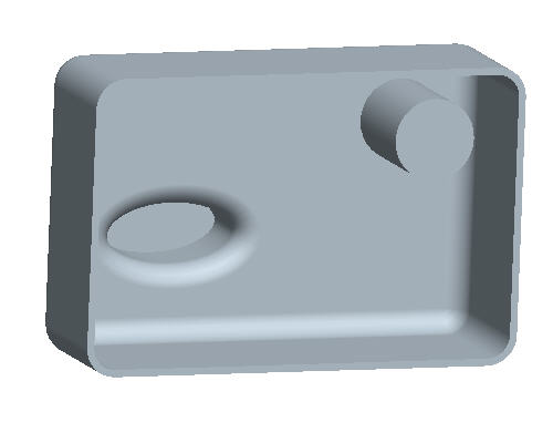
Sketch an ellipse roughly the size and location shown below.
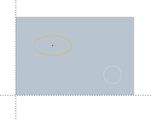
Click the Sketch Complete ![]() icon to complete the sketch.
icon to complete the sketch.
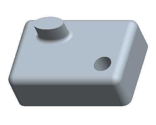
Press CTRL+D on the keyboard to return to the default orientation of the model and see the changes.
|
|
Notice that the rounds from the base of the original protrusion were automatically recreated at the base of this new protrusion. |
Press MIDDLE-DRAG to rotate the model and see the changes.
|
|
Middle-drag implies a middle mouse button "press and hold", while moving the mouse. |
Click Save ![]() from the main toolbar.
from the main toolbar.
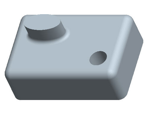
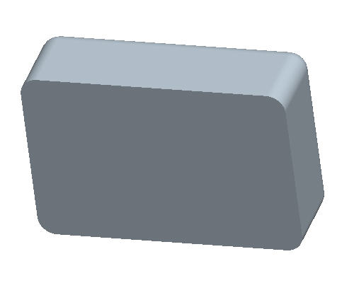
Congratulations! This completes the tutorial. The completed model is shown below.