
This tutorial is intended to be used alongside Pro/ENGINEER Wildfire 3.0 Tryout Edition and Pro/ENGINEER Wildfire 3.0 Commercial Edition.
Please make sure that Pro/ENGINEER Wildfire 3.0 Tryout (Commercial) Edition is installed on your machine before continuing. For Tryout Edition, files used or created during this tutorial cannot be used with commercial version of Pro/ENGINEER.
Your web browser and Pro/ENGINEER can be resized and laid out as shown below to facilitate your experience.
 Positioning Tutorial Window |
It is recommended that you maximize the amount of working area on your screen by setting your monitor to the highest resolution setting, for example 1600x1200.
Use the Commands at the top of the page to move navigate through the tutorial. Click Next to proceed to the next slide and Previous to return to the previous slide. Click Home to return to the beginning of the tutorial. If the page contains more information than the visible screen, a scroll bar will appear along the vertical side. Scroll through the entire contents before progressing to the next step.
You will see various icons throughout the tutorial:
There are several conventions used in this tutorial:
In this tutorial, you will learn the basics of Pattern Creation.
Step 1: Create a Dimension Pattern
Step 2: Create a Direction Pattern
Step 3: Create an Axial Pattern
Step 4: Create a Fill Pattern that patterns holes within an area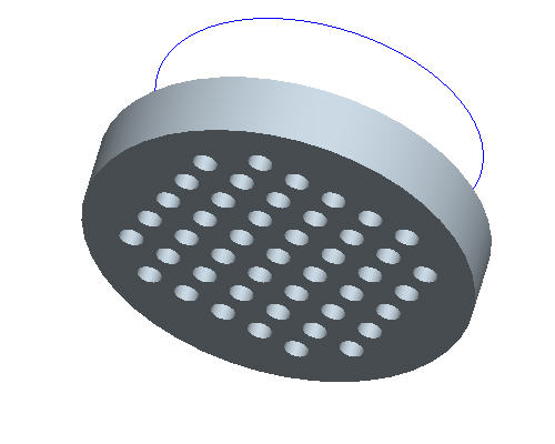
Step 5: Experiment with Fill Pattern shapes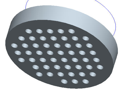
Step 6: Create a Fill Pattern that patterns protrusions within an area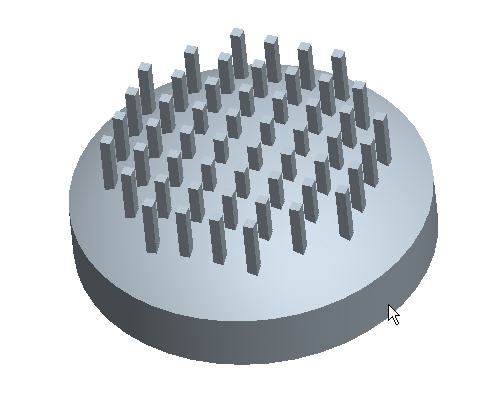
Step 7: Use the Fill Pattern to conform to surface topography
As an alternative to having this open along-side Pro/Engineer, you can also view a printable version by clicking here.
|
Task 1. Create Dimension Pattern. |
Start Pro/ENGINEER Wildfire 3.0 Tryout Edition if necessary.
If Pro/ENGINEER is already running ensure all windows are closed, and all items from the previous exercise are erased from memory.
In the Navigator Folder Browser ![]() , browse to the following folder C:\HANDS-ON_WF3\PATTERN_TUTORIAL.
, browse to the following folder C:\HANDS-ON_WF3\PATTERN_TUTORIAL.
Right-click the PATTERN_TUTORIAL folder and select Set Working Directory.
Click the Datum Planes ![]() , Datum Points
, Datum Points ![]() , and Coordinate Systems
, and Coordinate Systems ![]() icons in Pro/ENGINEER's main toolbar.
icons in Pro/ENGINEER's main toolbar.
|
|
These buttons toggle datum planes, axes, points and coordinate systems on and off so that your graphics window doesn't become too cluttered. |
Double-click PATTERNA.PRT to open it.
Click HOLE 1 from the model tree and click the Pattern ![]() tool from the feature toolbar.
tool from the feature toolbar.
|
|
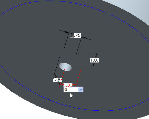
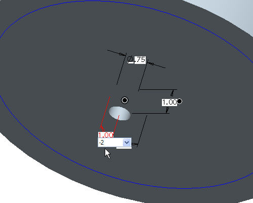
When the Pattern |
Select the horizontal 1.00 dimension as shown, type in -2 as the increment and press ENTER.
|
Task 2. Create Direction Pattern. |
Click Undo ![]() to remove the dimension pattern.
to remove the dimension pattern.
Right click HOLE 1 from the model tree and select Pattern.
In the dashboard, use the pull down to select Direction as the pattern option.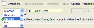
|
|
The Direction Pattern adds pattern members in one or two selected directions without requiring a specific dimensioning scheme on the original feature. |
Click the Datum Planes ![]() in Pro/ENGINEER's main toolbar to view the datum planes.
in Pro/ENGINEER's main toolbar to view the datum planes.
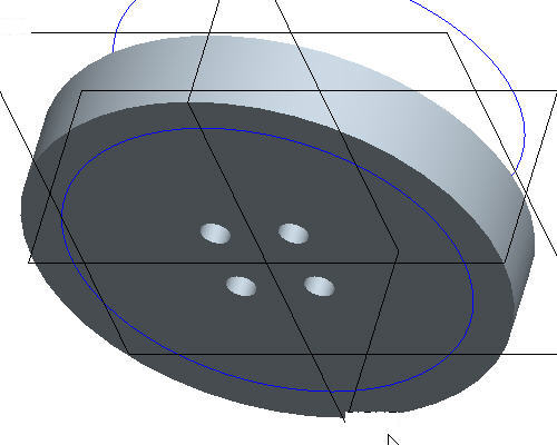
Select datum plane RIGHT as shown in the following figure.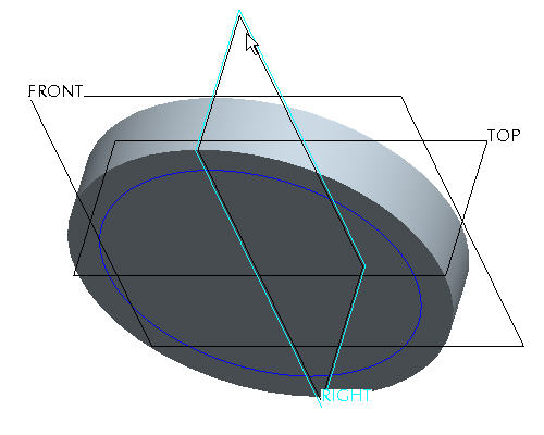
Select 1.18 dimension and type 2 as the increment and press ENTER.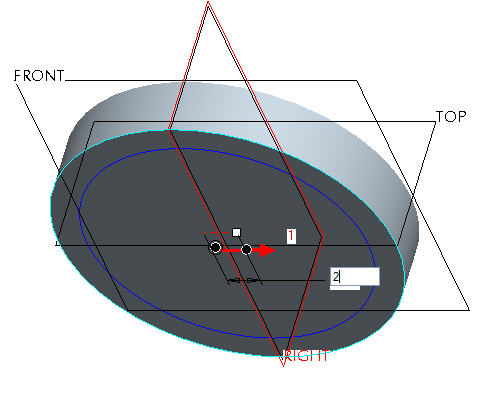
Press right mouse button and select Direction 2 Reference.
Select datum plane TOP, as shown in the following figure.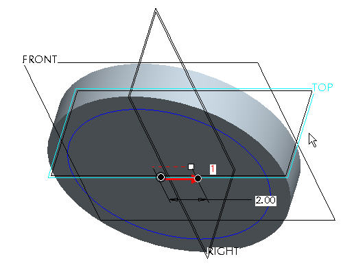
Select 1.18 and type 2 as the increment and press ENTER.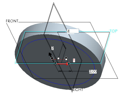
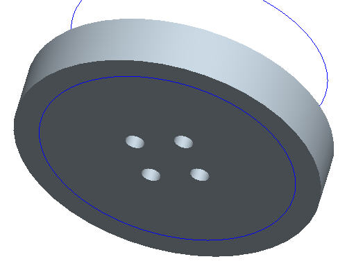
Click Complete Feature ![]() to see the 2X2 pattern.
to see the 2X2 pattern.
|
Task 3. Create Axial Pattern. |
Click Undo ![]() to remove the direction pattern.
to remove the direction pattern.
Right click HOLE 1 from the model tree and select Pattern.
In the dashboard, use the pull down to select Axis as the pattern option.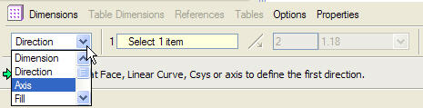
|
|
The Direction Pattern adds pattern members in one or two selected directions without requiring a specific dimensioning scheme on the original feature. |
Select the center axis of the part (A_2) to revolve the pattern around.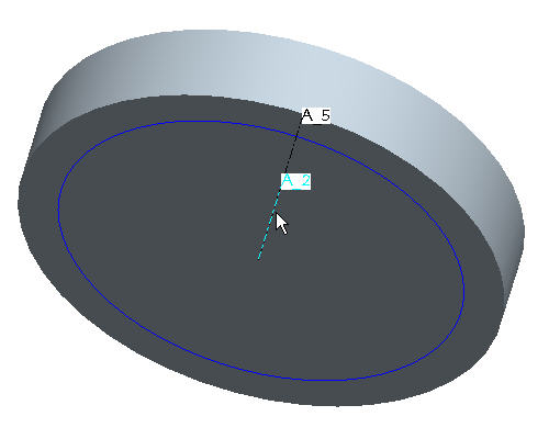
|
|
Make sure that the axes are displayed. If they are not, choose the Datum Axes |
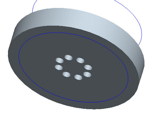
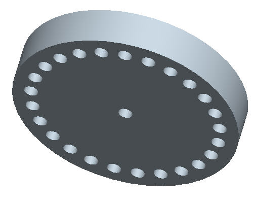
In the Dashboard, change the quantity of holes to 8. 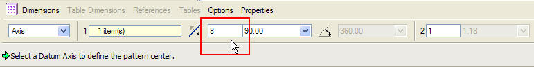
In the Dashboard, select Angular extents ![]() to equally space the members.
to equally space the members. 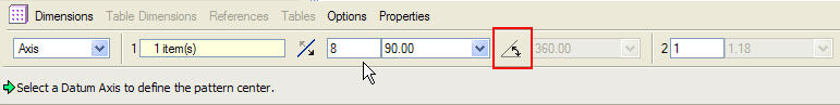
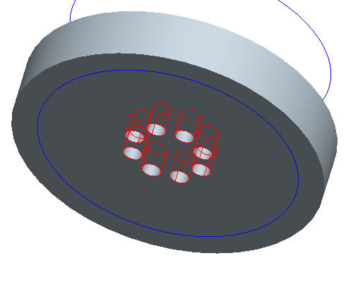
Click Complete Feature ![]() to see the axial pattern.
to see the axial pattern.
|
Task 4. Create a Fill Pattern that patterns holes within an area. |
Click Undo ![]() to remove the axial pattern.
to remove the axial pattern.
Right click HOLE 1 from the model tree and select Edit.
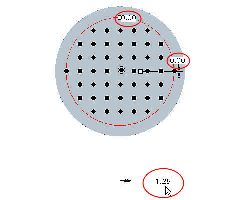
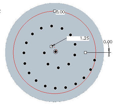
Double-Click on the horizontal and vertical offset values and change them from 1.00 to 0 and then choose the Regenerate ![]() icon. This will place the hole at the center of the part.
icon. This will place the hole at the center of the part. 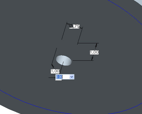
Right click HOLE 1 from the model tree and select Pattern.
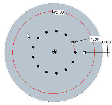
In the dashboard, use the pull down to select Fill as the pattern option.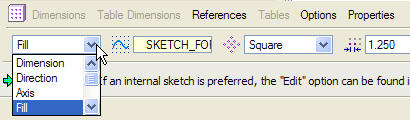
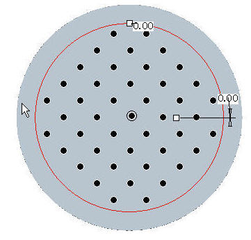
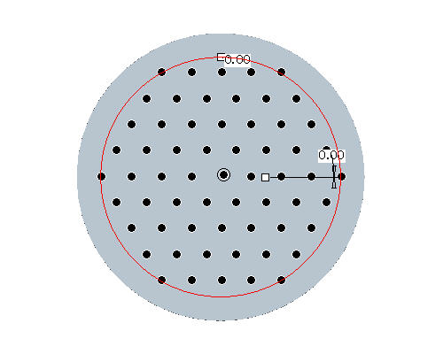
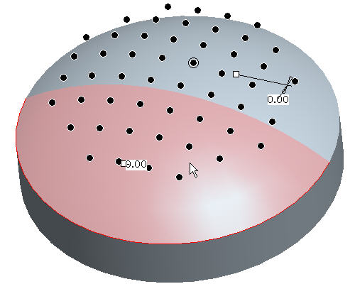
Pick the curve SKETCH_FOR_HOLE in the Model Tree. Notice the preview of black dots showing the locations where holes will be created.
Select the Saved View List ![]() icon in the main toolbar and select FRONT to change to the front view of the model. The pattern should look like the following figure.
icon in the main toolbar and select FRONT to change to the front view of the model. The pattern should look like the following figure.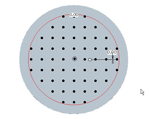
|
|
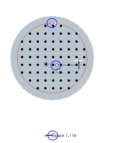
Individual hole members may be turned off by left clicking the black dot. The black dot turns white to indicate it will be excluded from the fill. To restore the pattern member, left click the white dot. |
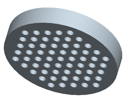
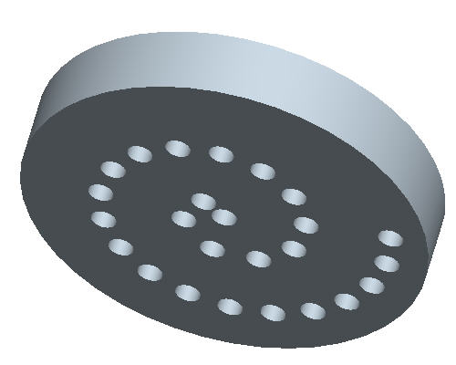
Click Complete Feature ![]() to see the fill pattern.
to see the fill pattern.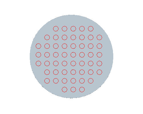
Select the No Hidden ![]() icon from the main toolbar to better see the pattern if necessary.
icon from the main toolbar to better see the pattern if necessary.
|
Task 5. Experiment with Fill Pattern shapes |
Select the Solid ![]() icon to return back to shaded mode if necessary.
icon to return back to shaded mode if necessary.
Right click on the PATTERN 1 of HOLE 1 in the model tree and select Edit Definition to change the existing pattern type.
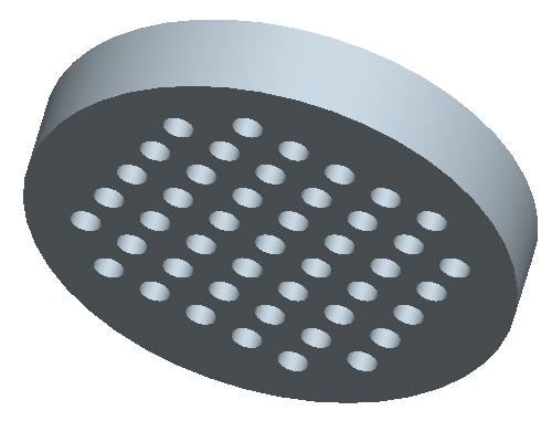
In the dashboard, change the pattern shape from Square to Diamond.
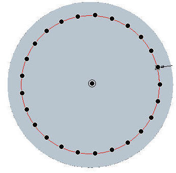
Click Complete Feature ![]() icon at the right side of the dashboard.
icon at the right side of the dashboard.
|
Task 6. Create a Fill Pattern of protrusions. |
Select Saved View List ![]() icon from the main toolbar to reorient the model to a better view and select BACK_PATTERN.
icon from the main toolbar to reorient the model to a better view and select BACK_PATTERN.
If Axes are showing from the holes on the other side, hide them by choosing Datum Axes ![]() .
.
Right click on PROTRUSION1 in the Model Tree and choose Pattern.
In the Dashboard, change the Dimension pattern option to Fill as in the previous task.
Select the curve SKETCH_FOR_PROTRUSION in the model tree and select the Complete Feature ![]() icon at the right side of the dashboard to complete the pattern.
icon at the right side of the dashboard to complete the pattern.
|
|
Rotate the model by holding the middle mouse button and dragging. Notice how all of the protrusions start at the same plane. |
|
Task 7. Fill Pattern along a curved surface. |
|
Task 7. Fill Pattern along a curved surface (continued). |
Select Saved View List ![]() icon and select BACK_PATTERN to return back to the previous orientation.
icon and select BACK_PATTERN to return back to the previous orientation.
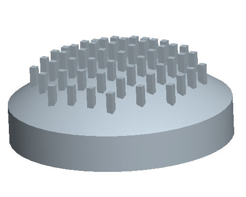
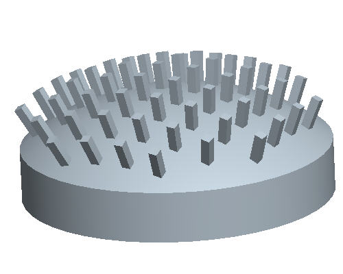
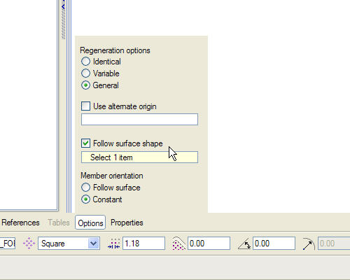
Right click on PATTERN2 of PROTRUSION1 in the Model Tree and select Edit Definition.
Select the Options tab from the Dashboard at the bottom of the screen.
Change the radial button from Constant to Follow Surface Shape. 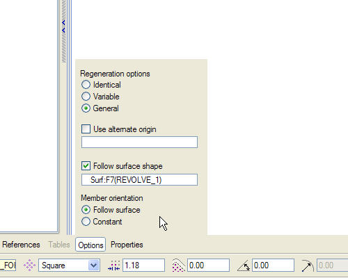
Select Complete Feature ![]() icon at the right side of the dashboard.
icon at the right side of the dashboard.
Congratulations! This completes the Pattern Tutorial.