 |
|
|
Creating the CONNECTING ROD
We will create the body of the CONNECTING_ROD using an oval-shaped sketch and extrude. |
|
| Task 2-15. Create the CONNECTING_ROD and begin a sketch. |
- Click Datum Planes
 from the main toolbar to enable their display. from the main toolbar to enable their display.
- Click New
 from the main toolbar and select Part as the Type. from the main toolbar and select Part as the Type.
- Type CONNECTING_ROD as the Name and press ENTER
- Start the Sketch Tool
 from the feature toolbar. from the feature toolbar.
- Select datum plane FRONT from the model.
- Click Sketch from the Sketch dialog box.
- Click Datum Planes from the main toolbar to disable their display.
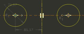
- Begin the sketch of an oval by sketching two circles as shown in the following figure:
- Click Centerline
 from the sketcher toolbar. Sketch a centerline by clicking two locations on the vertical reference. from the sketcher toolbar. Sketch a centerline by clicking two locations on the vertical reference.
- Click Circle
 from the sketcher toolbar. Click a location on the horizontal reference for the center of the left circle, then complete the circle. from the sketcher toolbar. Click a location on the horizontal reference for the center of the left circle, then complete the circle.
- Click a location on the horizontal reference for the center of the right circle, then move the mouse outwards until the radius snaps to the radius of the first circle, then click again to complete it.
- Click Constraints
 from the sketcher toolbar. from the sketcher toolbar.
- Click Symmetric
 , and select the center of each circle and then the centerline. , and select the center of each circle and then the centerline.
- Click Close from the Constraints dialog box.
Sketching Circles | |
