|
Creating a Feature with an Internal Sketch and Embedded Datum Plane
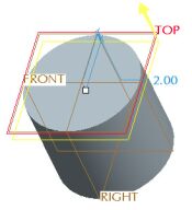
The next solid feature to be created is an Extruded Cut to hollow out the PISTON. In order to capture the desired dimensioning scheme for the cut, its sketch will be placed on a datum plane offset from the top surface of the model.
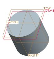
We will start the Extrude tool and create an internal sketch and a datum plane with the Extrude dashboard open. When the Extrude tool is completed, the system automatically places the sketch and datum plane in a branch within the extrude feature in the model tree. This technique allows us to edit and manipulate several features as one. |