Machining Features

A machining feature defines a closed volume that represents the material that must be removed to produce the finished feature of the part.

It consists of faces derived from the design model (Hard Walls), and work piece model (Soft Walls), with respect to the machine orientation and any adjacent features.

It is important to note that tool path information is NOT automatically assigned to a feature. Tool paths are defined independently, providing full control over the machining of the features. You may be able to machine some features with a single tool path. Others might require 2 or more tool paths. Only you can make these decisions.

The order of feature definition and the types of features used, will establish the sequence of material removal. Doing this correctly, is the most important step in determining the overall efficiency of the part program. The way each individual feature is actually machined is determined at the tool path level.


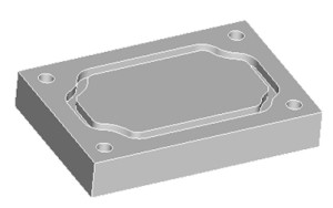
 The concept of a machining feature is a simple. If you subtract the design model from the workpiece model, the difference is the total volume of material that must be machined away.  But that volume in and of itself is very unwieldy. In all but simple cases, any attempt to machine that volume directly will result in disorder.

Machining features provide the NC programmer an easy, efficient, intuitive method of breaking down the volume into smaller, more manageable volumes that have machining relevance.

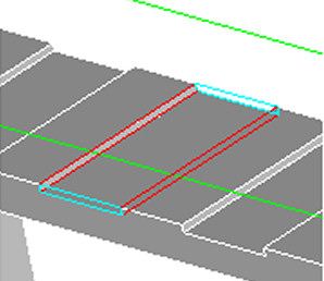
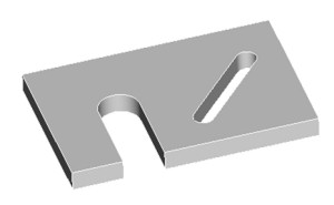
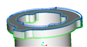
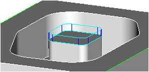
By defining features such as faces, pocket, slots, channels,etc...the NC programmer re-classifies the material into smaller volumes.Since these features are all based on shop-floor machining methodologies, they are very recognizable and therefore more easily and efficiently machined.

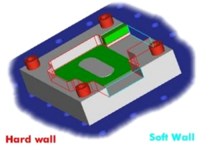
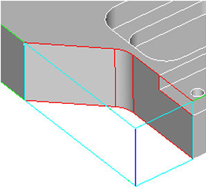
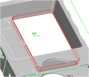
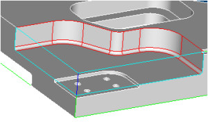
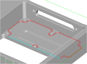
There are 18 features, each with its own unique characteristic and purpose based on a combination of hard walls, soft walls and floor parts.

 Face

  • Establishes the top of the part with respect to the current spindle orientation
  • All soft walls
  • Select the hard floor and the system will find the outermost loop
 

 Slab

  • In its simplest form, it is a face with bosses on it.
  • More complex variations can have a hard wall
  • Include a hard floor
 

 Pocket

  • A single chain of hard-wall
  • A pocket has a hard-floor
 

 Profile

  • Form 1 : a single chain of soft walls and a single chain of hard walls that together form a closed loop
  • Form 2 : a single chain of soft walls and a single chain of hard walls that intersect to each form a closed loop
  • Soft floor (through feature)
 

 Thru Pocket

  • A single chain of hardwalls
  • A thru pocket has a soft floor
 

 Step

  • Form 1 : a single chain of soft walls and a single chain of hard walls that together form a closed loop
  • Form 2 : a single chain of soft walls and a single chain of hard walls that do not intersect and that each form a closed loop
  • Hard floor
 

 Channel

  • Multiple alternating hard and soft walls that together form a close loop
  • At least two walls of each type are required
  • Hard floor
 

 Slot

  • Three variations of slot features
  • An end slot is either soft or a full radius
  • Side wall of a slot are constant normal offsets of each other
  • Hard floor
 

 Thru Slot

  • One soft wall
  • No soft walls
  • Soft floor
 

 Flange

  • An outer loop of soft walls
  • An inner loop of walls that may be hard or soft
  • Hard floor
 

 Boss Top

  • A single chain of soft walls that form a closed loop
  • The first closed loop found after selecting the floor is the one that will be used
  • Hard floor
 

 O-ring Groove

  • Constant cross section grooves on face
 

 Top Round

  • Removes material along a chain of horizontal rounded wall
  • The rounded surfaces are the floor of the feature
  • Can be machined with a corner rounding or sketch tool
 

 Chamfer

  • Removes material along a chain of horizontal chamfered edges
  • The chamfered surfaces are the floors of this feature
  • Can be machined with a chamfering or countersink tool


 Undercut

  • Open volume with hard ceiling
  • Can be cut in single or multiple pass
 

 Rib top

  • Used to machine the top of a rib
  • The top of the rib is the floor of the feature
  • Material removal only above the rib
 

 Hole Pattern

  • A set of one or more holes
  • Floor can be soft (through) or hard (blind)
 

 Entry Hole

  • A single hole created in an existing pocket,through pocket or in a slot with hard wall
  • Facilitate cutting tool entry into the features with hard wall
  • Floor Can be soft (through) or hard ( blind)


© PTC Product Management