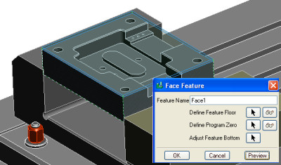
Creating a Step feature
The purpose of a step feature is for general material removal that takes place on the edge of the part or on the edges of other features.
There are two possible forms of a step feature. Both forms have a hard floor:
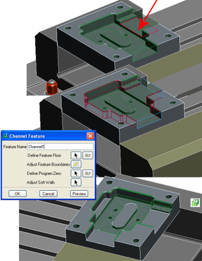
- Form 1 consists of a single chain of hard wall and a single chain of soft walls that together form a closed loop.
- Form 2 consists of a single chain of hard wall that forms a closed loop in and of itself and a single chain of soft walls that form a closed loop in and of itself. These two loops do not intersect each other.
In our case, the step we are going to create is type 1.
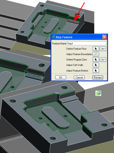
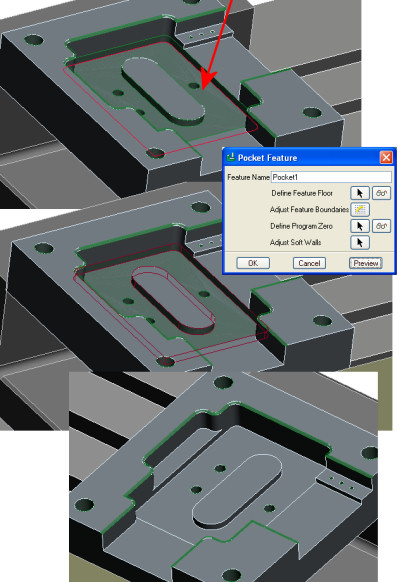
- Choose the Step icon
 or NC Create / Features / Step or NC Create / Features / Step
- Select the top face of the step on the side of the channel feature.
- Select OK then Done/ Return to come back to the Channel Feature dialog
- Select Preview to see the detected step feature with soft blue wall and one red hard wall
- Select OK to create the feature.
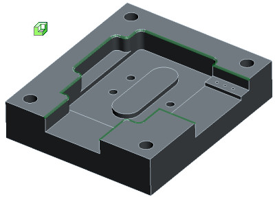
The material removal icon  allows you to toggle the stock model to display its current state taking in to account all the machining features created. allows you to toggle the stock model to display its current state taking in to account all the machining features created. |

 Printable view