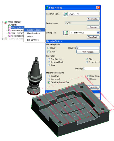
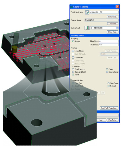
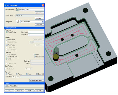
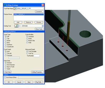
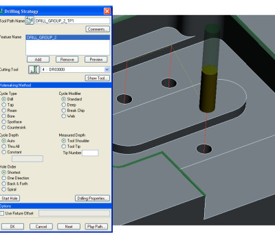
Exercise 3 - Creating Basic ToolpathsIn this exercise you will learn how to create toolpaths for the machining features defined in the previous exercise. Retrieve
Save
|
| CAM Lite |
 |
| Introduction to CAM Lite - Page 6 / 7 |
| CAM Lite |
|
| Introduction to CAM Lite - Page 6 / 7 |
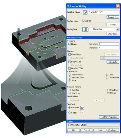
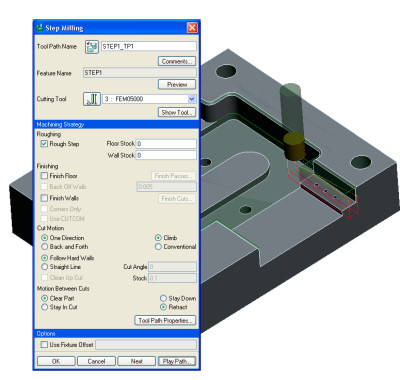
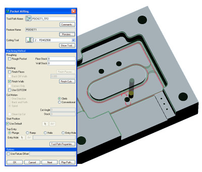
Exercise 3 - Creating Basic ToolpathsIn this exercise you will learn how to create toolpaths for the machining features defined in the previous exercise. Retrieve
Save
|
 Printable view