Exercise 4 - CAM-Lite Advanced Functionality
In this exercise we will look at some of the advanced functions of CAM-Lite including :
- Outputting CL data
- Customizing toolpaths
- Using manufacturing templates
- Creating advanced machining features and toolpaths.
Retrieve  in Pro/ENGINEER the XM1.mfg model saved in exercise 3. in Pro/ENGINEER the XM1.mfg model saved in exercise 3.
Outputting CL Data
CAM-Lite does not include post-processor and provides only an APT based CL data output. This standard format can be used with commercial post-processor or with GPOST included in full Pro/ENGINEER NC Licenses. The file extension for CL data is .ncl
A basic G code output, based on a hard coded post-processor demonstrates the NC code output from CAM-Lite.
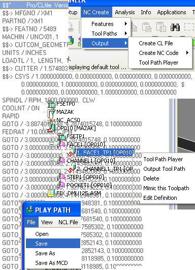
There are multiple ways to output a CL data :
- Select the operation OP010 or an individual toolpath from the model tree, right-click Output Toolpath
- Select the operation OP010 or an individual toolpath from the model tree, right-click Toolpath Player From the toolpath player dialog, select File / Save (we will use the current name of the toolpath with extension ncl) or Save As (to control the name) to output the CL data in a file.
|

|
By default the CL data is written in the current working directory. You can control the location where the CL data is written with the config.pro option pro_mf_cl_dir
In a data management environment, this config.pro option can point to your workspace. |
- Select one toolpath or the operation in the model tree, then NC Create / Output / Create CL file
You can also access the CL player from this pull down menu.
|
|
To output the default G code based on the internal post-processor, select one or multiple toolpaths in the model tree, then NC Create / Output / Create NC Code / Automatic. This will create a file with extension "tap". |
|
|
 |
Advanced Toolpath Properties
Up until now, in all the exercises, we have re-used the same default values for the toolpath properties including cutting conditions and approach/exit strategies. These properties are controlled for each toolpath using the Toolpath Properties dialog.
- Select the FACE1_TP1 toolpath feature in the model tree and right on Edit Definition. This brings us back to the Face Milling dialog.
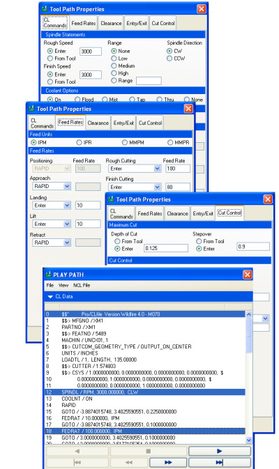
- Select Tool Path Properties we are going to change the feed rate and spindle speed. and the step over controlling the toolpath strategy :
- Change Spindle speed values for both Rough and Finish speed to 3000
- Select Feed Rates tab and change Rough Cutting Feed rate to 100, Finish Cutting feed rate to 80 and keep Landing and Lift feedrates to 10.
|
|
Feed rate can automatically be taken from a tool/material database using the "From Tool" option in the pull down menu for Rough and Finish cutting. This requires setting up these libraries and is not covered in this tutorial. |
- Select Cut Control tab and change Stepover to .9".
|

|
By putting your mouse over the parameter name you will see a description of the parameter :
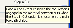
|
- Select OK to exit the ToolPath Properties dialog and then Play Path to see the effect of your changes. Open (Click the arrow)
 the CL Data display to see the resulting SPINDL and FEDRAT statements the CL Data display to see the resulting SPINDL and FEDRAT statements
- Close the CL player , and then OK to validate your changes and update the face milling feature.
Save  the model XM1.mfg the model XM1.mfg |
|
 |
Using Templates
Up until now, each time we have defined a toolpath we started from the internal defaults of the system. However, it is possible to capture toolpath information (cutting tool, machining options and toolpath properties) in a template and re-use it to create new toolpaths or setup defaults for machining features.
Start by retrieving in Pro/ENGINEER the XM2.mfg model. Some Machining features and toolpaths have already been created in this model.
We will start by creating from scratch a pocket machining toolpath.
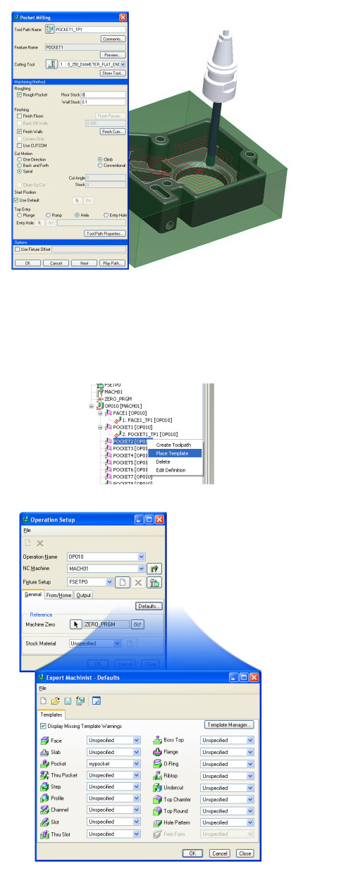
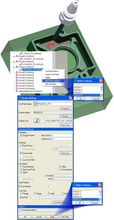
- Select the POCKET1 feature in the model tree, right-click on the mouse, Create Toolpath. This brings the Pocket Milling definition dialog with the internal defaults.
- Select 0)250_DIAMETER_FLAT_ENDMILL from the Cutting Tool pull down
- We will do both roughing and finishing. For the roughing toolpath, we will leave a stock of 0.1" on the wall and no stock on the floor.Set Floor Stock to 0 and Wall Stock to 0.1"
- Select Finish Walls
- Set Helix for entry strategy
- Keep the other default
- Select Play path to see the results
- In Play Path select the right arrow
 to start the simulation to start the simulation
- Close Play Path when finished to come back to the toolpath creation dialog
- To capture the current process in a template use
 in the Pocket Milling dialog to save the strategy. Set the name to mypocket. This will create a template file with the extension .tpl. in the Pocket Milling dialog to save the strategy. Set the name to mypocket. This will create a template file with the extension .tpl.
|
|
Templates are stored in the working directory in the path defined by the config.pro mfg_template_dir |
- Select OK to create the toolpath feature
We are now going to re-use this template to create the toolpath for POCKET2.
- Select the POCKET2 feature in the model tree, right-click on Place Template. Select the mypocket template created in the previous step, then Open. This brings you to the Pocket Milling definition dialog with the defaults based on the mypocket template.
- Select Play path to see the results
- In Play Path select the right arrow to start the simulation
- Close Play Path when finished to come back to the toolpath creation dialog
- Select OK to create the Toolpath feature.
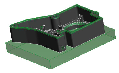
- The stock model is updated to display the result of the Toolpath. All the material in the Pocket feature has been removed.
You can setup this template to be the default for all your pocket creations from the operation manager.
- Select OP010 in the model tree, right-click on Edit Definition.
- Select Defaults in the Operation Setup dialog
- From the Pocket pull down, select mypocket as default for this toolpath feature
- Then OK to exit the Defaults dialog and OK to exit the Operation dialog.
Let's now check the default by creating a new toolpath on POCKET3 feature.
- Select POCKET3 feature from the model tree, right-click and select Create Toolpath.
- Check the defaults in the Pocket Milling dialog, so that they match the defaults from the template
- Select Play path to see the results
- In Play Path select the right arrow to start the simulation
- Close Play Path when finished to come back to the toolpath creation dialog
- Select OK to create the toolpath feature.
Save the model XM2.mfg |
|
 |
NEXT and MIMIC
We are now going to look at some techniques to streamline the development on toolpaths in CAM-Lite.
- First let's look at how to re-use an existing toolpath with the MIMIC command.
- Select POCKET3_TP1 toolpath feature, right-click on Mimic This Toolpath
- A list of available machining features that can use this toolpath strategy appears. Select POCKET4 then OK
- The Pocket Milling dialog appears
- Check if the defaults in the Pocket Milling dialog match the settings from POCKET3_TP1 toolpath
- Select Play path to see the results
- In Play Path select the right arrow to start the simulation
- Close Play Path when finished to come back to the toolpath creation dialog.
- To continue to use the same strategy for another pocket, select NEXT in the Pocket Milling dialog, the POCKET4_TP1 feature is created and a list of available machining features appears:
- Select POCKET5
- Continue with NEXT for all the POCKET features in the model
- Select OK to create the last pocket toolpath feature.
Save the model XM2.mfg |
|
 |
Advanced Machining Features
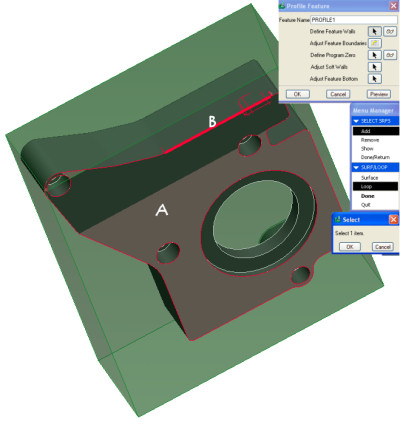
We are now going to create a profile feature to control the depth.
- Select
 the Profile feature icon. the Profile feature icon.
- Select the Loop option in the SURF/LOOP menu
- Select the bottom surface (A) of the reference model and then one of the side edges (B), then click OK, done, done to come back to the Profile Feature dialog.
- The profile feature goes through the complete part. In the real world, we need to put the part in a vise and to keep some stock under the model.
- Select Adjust Feature Floor and then set Use Datum Plane before selecting the bottom floor of the model.
- Select OK to exit the Adjust Feature Dialog and OK to create the feature.
The material removal icon  allows you to toggle the stock model to display its current state taking in to account all the machining features created. allows you to toggle the stock model to display its current state taking in to account all the machining features created.
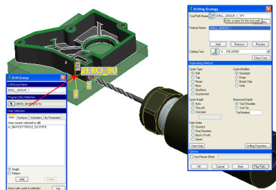
CAM-Lite also works in 4- and 5-axis positioning. Features can be created on any orientation space but the final 2 1/2 axis toolpath will keep a constant tool vector. Let's create a feature and machine the hole on the side of the part.
- In Play Path select the right arrow to start the simulation
- Close Play Path when finished to come back to the toolpath creation dialog
- Select OK to create the toolpath feature.
Save the model XM2.mfg |
|
|
|

 Printable view