Task 1. Launch Pro/ENGINEER and import the AutoCAD DWG file
|
|
Drawings are representations in 2D of 3D geometry. Therefore, it sometimes makes sense to reuse that information when moving to a 3D solid model-centric approach. You will begin by importing an AutoCAD 2D drawing into Pro/ENGINEER, then use two of the views to create a new, 3D part. |
-
Start Pro/ENGINEER Wildfire 4.0 Tryout Edition if necessary.
-
If Pro/ENGINEER is already running, close all windows then remove all objects from session using File > Erase > Not Displayed...
-
File > Set Working Directory..., browse to HANDS-ON_WF4\07-2D_LEGACY.
-
Click Open
 from the main toolbar.
 -
From the File Open dialog box, use the Type drop down list to select All Files (*).
-
Select SAMPLE.DWG and select Open in the dialog box.
-
Select OK in the Import New Model dialog box to accept the default type and name
-
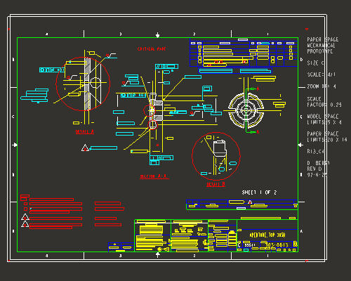
Select OK in the Import DWG to accept the default import options. The drawing will be created from the dwg and will appear as shown in the figure below.

The file imported above is a native AutoCAD .dwg file. Pro/ENGINEER supports reading and writing of native .dwg files and .dxf files. Other 2D and 3D formats Pro/ENGINEER supports include: IGES, CGM, STEP, STL, VRML, Parasolids, ACIS and many others.
-
Click Zoom In
 from the main toolbar and left to select the zoom box start point and left click for the zoom box end point. The zoom area will appear similar to the figure shown below.
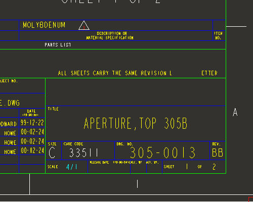
-
Note the scale of the drawing is 4/1. This will be important when using the drawing to create the model.
-
Select Refit
 from the main toolbar to return to the full display.