This tutorial opens a non-native drawing file in Pro/ENGINEER and uses sketches from the drawing views to create solid geometry.
Task 1: Launch Pro/ENGINEER and import the AutoCAD DWG file
Task 2: Use layers to blank the extraneous drawing entities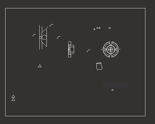
Task 3: Create a new Pro/ENGINEER part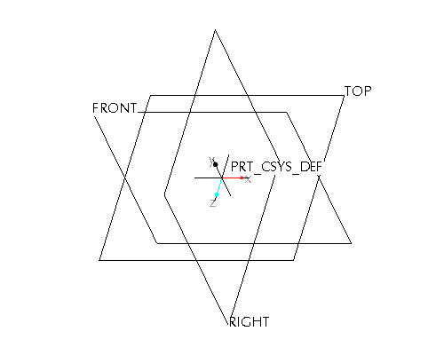
Task 4: Use the front view from the drawing as the front sketch of the part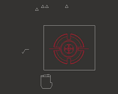
Task 5: Use the side view from the drawing as the side sketch of the part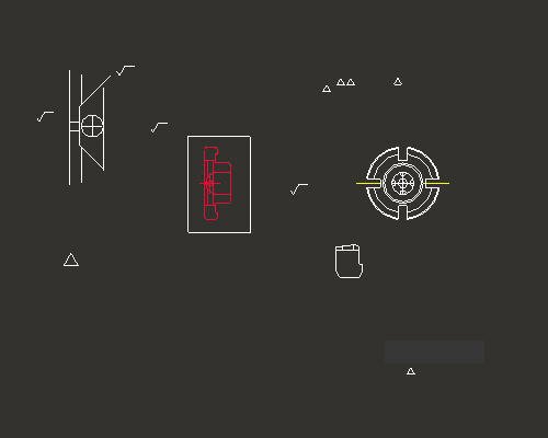
Task 6: Create the first solid feature as a revolve of the side sketch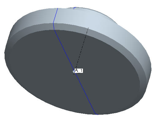
Task 7: Change the part color to transparent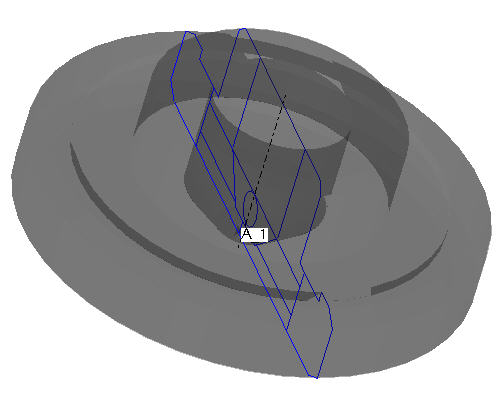
Task 8: Add radial holes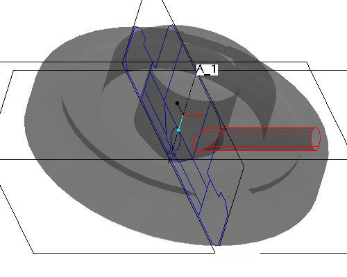
Task 9: Create the slot cuts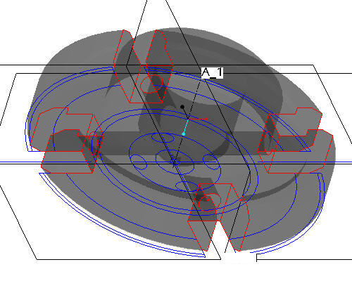
Task 10: Change the appearance of the model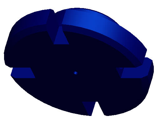

|
|
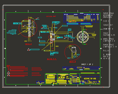
Drawings are representations in 2D of 3D geometry. Therefore, it sometimes makes sense to reuse that information when moving to a 3D solid model-centric approach. You will begin by importing an AutoCAD 2D drawing into Pro/ENGINEER, then use two of the views to create a new, 3D part. |
Start Pro/ENGINEER Wildfire 4.0 Tryout Edition if necessary.
If Pro/ENGINEER is already running, close all windows then remove all objects from session using File > Erase > Not Displayed...
File > Set Working Directory..., browse to HANDS-ON_WF4\07-2D_LEGACY.
Click Open ![]() from the main toolbar.
from the main toolbar.
From the File Open dialog box, use the Type drop down list to select All Files (*).
Select SAMPLE.DWG and select Open in the dialog box.
Select OK in the Import New Model dialog box to accept the default type and name
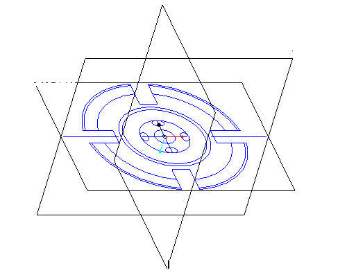
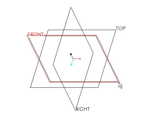
Select OK in the Import DWG to accept the default import options. The drawing will be created from the dwg and will appear as shown in the figure below.
|
|
The file imported above is a native AutoCAD .dwg file. Pro/ENGINEER supports reading and writing of native .dwg files and .dxf files. Other 2D and 3D formats Pro/ENGINEER supports include: IGES, CGM, STEP, STL, VRML, Parasolids, ACIS and many others. |
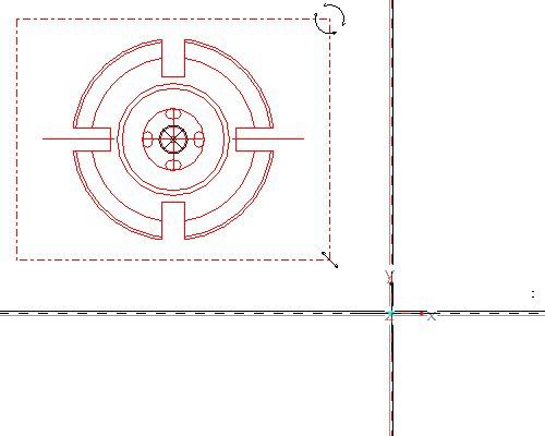
Click Zoom In ![]() from the main toolbar and left to select the zoom box start point and left click for the zoom box end point. The zoom area will appear similar to the figure shown below.
from the main toolbar and left to select the zoom box start point and left click for the zoom box end point. The zoom area will appear similar to the figure shown below.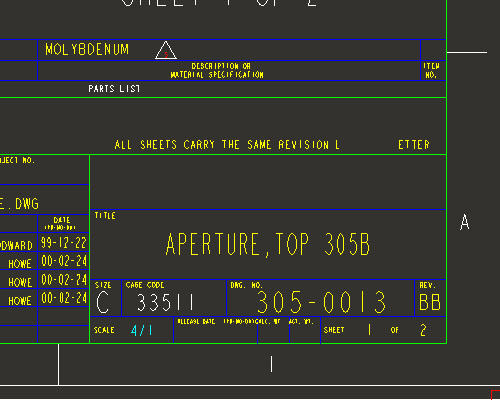
Note the scale of the drawing is 4/1. This will be important when using the drawing to create the model.
Select Refit ![]() from the main toolbar to return to the full display.
from the main toolbar to return to the full display.
|
|
Imported .dwg files maintain their AutoCAD layering scheme. Simply blank all the layers and show only the layer that has the relevant entities desired for creating the solid 3D geometry. |
In the Navigator Browser panel on the left, right click on LAYERS and select Hide.
Scroll down the Navigator Browser Panel, right click on LINE_M and select Unhide.
Click Save ![]() from the main toolbar and OK in the Save dialog box.
from the main toolbar and OK in the Save dialog box.
Click the New ![]() icon on the main toolbar and notice that Part is selected as the Type in the New Object dialog box.
icon on the main toolbar and notice that Part is selected as the Type in the New Object dialog box.
In the New dialog box, type SAMPLE as the Name.
Note that the Use Default Template option is enabled. Uncheck Use Default Template and click OK.
Select inlbs_part_solid as the template.
Type your initials in the value box for MODELED_BY and click OK.
|
|
Draft entities from drawing views can be imported into a sketch feature in Part Mode. The sketch feature is used to define the shape dimensions and general placement of a sketch-based feature such as a protrusion or cut. |
Select Coordinate Systems ![]() in the main toolbar to disable their display.
in the main toolbar to disable their display.
Select the FRONT datum plane from the window.
|
|
To select a feature, move the cursor over the feature until it turns blue. Then select the feature using the left mouse button. The selected feature will be highlighted in red. |
Select the Sketch Tool ![]() icon on the right toolbar to create a sketch.
icon on the right toolbar to create a sketch.
|
|
The Sketch Tool allows the user to define a shape using 2-D entities that can be used later to create a sketched feature |
Accept the default sketching plane and orientation plane and select Sketch from the Sketch dialog in the upper right corner of the screen. This brings you into the sketch tool.
Select the Sketch from the pull down across the top of the window and select Data from File and File System...
From the File Open dialog box, use the Type drop down list to select Drawing (*.drw).
Select SAMPLE.DRW and Open.
Press and hold the left mouse button and drag a selection box around the drawing view shown in the figure below. Release the left mouse button to close the selection box.
From the Select dialog box, select OK.
Select anywhere in the sketching window to place the copied section. The section will appear similar to the figure below.
|
|
When importing a sketch into the sketcher environment, the scale/rotate preview step allows you to reposition, resize and rotate the entities prior to applying sketcher dimensions. There are three anchors that can be used: The "X" anchor is position, the circular arrows are rotation, and the linear arrows are for scale. Holding down the left mouse button and dragging on any one of these icons will affect the imported entities. In the next section you'll learn how to move the anchors around to change the action points. |
Press and hold left mouse button on the X anchor at the center of the pasted sketch and drag the section to the center of the datum planes. Release the left mouse button when the pasted sketch is in position. Note the anchor should snap to the intersection of the datum planes. Move the pasted sketch as shown in the figure below.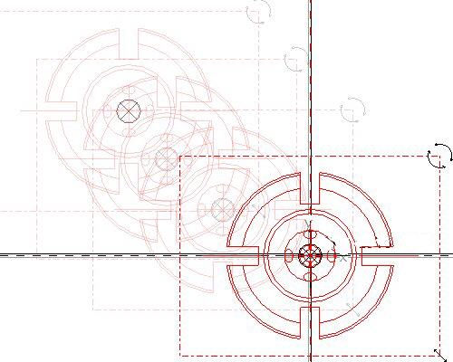
In the Scale Rotate dialog box, type 0.25 as the scale.
|
|
The drawing scale was 4:1, therefore we need to scale the copied sketch by 0.25 to get a 1:1 model size. |
Select Accept Changes ![]() in the Scale Rotate dialog box.
in the Scale Rotate dialog box.
Select Refit ![]() from the main toolbar to see the imported sketch. Note that the system automatically dimensions the sketch and there are no manual dimensions required.
from the main toolbar to see the imported sketch. Note that the system automatically dimensions the sketch and there are no manual dimensions required.
Select Complete Sketch ![]() on the right side toolbar.
on the right side toolbar.
Select CTRL+D to return to the default view.
Right click SKETCH 1 from the model tree and select Rename.
Type FRONT-SECTION as the new name.
|
|
Renaming the features in the model tree provides for clarity and quick access to select features when needed. |
|
|
Toggle Datum Planes |
|
|
Now that the front view is available, place the side view in an appropriate position on an orthogonal plane. |
Left click on the RIGHT datum plane in the window. Note it will turn red when it is selected as shown in the figure below.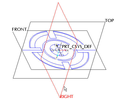
Click the Sketch Tool ![]() icon on the right toolbar to create a sketch.
icon on the right toolbar to create a sketch.
|
|
The Sketch Tool allows the user to define a shape using 2-D entities that can be used later to create a sketched feature |
Accept the default sketching plane and orientation plane and click Sketch from the Sketch dialog in the upper right corner of the screen. This brings you into the sketch tool.
Click the Sketch from the pull down across the top of the window and select Data from File and File System...
From the File Open dialog box, use the Type drop down list to select Drawing (*.drw).
Select SAMPLE.DRW and Open.
The previous selected section remains highlighted in red to indicate that it has been selected already. Click Repaint ![]() in the main toolbar.
in the main toolbar.
Press and hold the left mouse button and drag a selection box around the drawing view shown in the figure below. Release the left mouse button to close the selection box.
From the Select dialog box, select OK.
Left click anywhere in the sketching window to place the copied section. The section will appear similar to the figure below.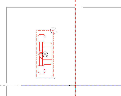
|
|
In the last section you learned how to move the imported sketch using the "X" anchor and saw how it snapped to the datum planes. In this situation however, you would like the point that snaps to the datum planes to be different than its default location. Any of the anchors can be moved around by holding down the right mouse button and dragging them. |
Click Zoom In ![]() from the main toolbar and left click to provide a start point to the zoom box around the middle of the pasted sketch and left click to provide an end point to the zoom box. Right click to exit the Zoom command.
from the main toolbar and left click to provide a start point to the zoom box around the middle of the pasted sketch and left click to provide an end point to the zoom box. Right click to exit the Zoom command.
Press and hold Right mouse button and drag the ![]() anchor to the middle of the left most edge of the section as shown in the figure below.
anchor to the middle of the left most edge of the section as shown in the figure below.
|
|
Only the Right mouse button will relocate the Move anchor. Relocate the Move anchor until a "M" appears. This indicates that the anchor is snapped to the midpoint of the selected edge. |
Click Sketch Orientation ![]() icon to see the entire sketch.
icon to see the entire sketch.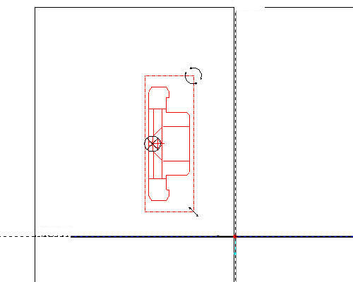
In the Scale Rotate dialog box, type 0.25 as the Scale value and 90 as the Rotate value.
|
|
The drawing scale was 4:1, therefore we need to scale the copied sketch by 0.25 to get a 1:1 model size. |
Press and hold left mouse button and drag the X anchor to intersection of the datum planes as shown in the figure below. 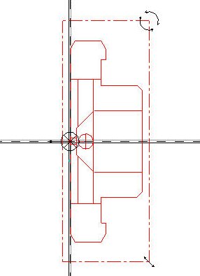
Click Accept Changes ![]() in the Scale Rotate dialog box. Sketch should appear as shown in the figure below.
in the Scale Rotate dialog box. Sketch should appear as shown in the figure below.
|
|
The 90 degree rotation of the section orients it correctly with respect to the front section you placed in the previous step. Of course this could also have been accomplished by rotating the sketch plane setup, but for the simplicity of this tutorial it was decided to do that here instead. |
Click Complete Sketch ![]() on the right side toolbar.
on the right side toolbar.
Click CTRL+D to return to the default view.
Right click SKETCH 1 from the model tree and select Rename.
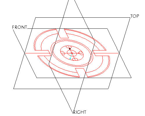
Type SIDE-SECTION as the new name. The part should look like the figure shown below.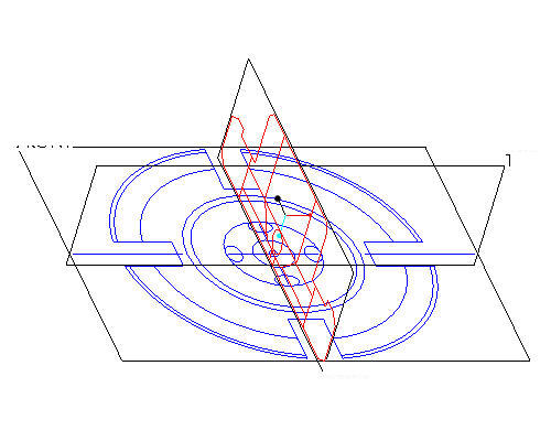
|
|
Renaming the features in the model tree provides for clarity and quick access to select features when needed. |
|
|
Creating solid geometry normally involves sketching a shape and extruding, revolving or sweeping it. Using a 2D view from a drawing is no different. In this task we'll revolve a portion of the side view around an axis to create a solid. |
|
|
The revolve feature will require an axis to revolve about. We can create the center axis before or after the sketch is created, for simplicity we will create the axis first. |
Left click on the RIGHT datum plane in the window.
Press and hold CTRL key on the keyboard and left click on the TOP datum plane. Note both will turn red when it is selected as shown in the figure below.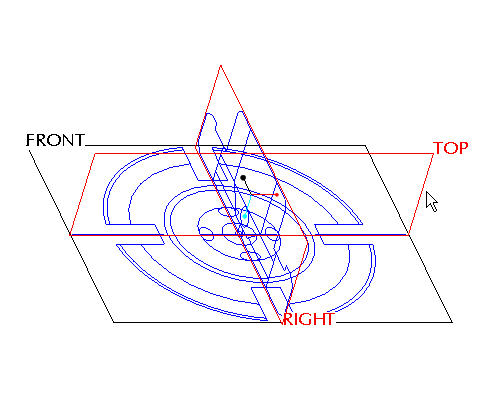
Click Create Datum Axis ![]() icon on the right side toolbar.
icon on the right side toolbar.
|
|
Do not confuse the datum creation tools usually located on the right side toolbar with the datum visibility tools usually located on the main toolbar. Notice that the visibility tools have a small eye on them -- for example |
Right click on FRONT-SECTION from the model tree and select Hide to reduce confusion while creating the revolve shape.
|
|
We do not want to revolve the entire sketch, but only a part of it, so we'll use what is already there as the basis for a new sketch. |
Left click on the RIGHT datum plane in the window.
Click the Sketch Tool ![]() icon on the right toolbar to create a sketch.
icon on the right toolbar to create a sketch.
In the Sketch dialog, accept the select references and select Sketch button to close the dialog.
Click the Datum Planes ![]() icon to hide the datum planes.
icon to hide the datum planes.
Select the Use Edge ![]() icon from the sketch toolbar. In the Type dialog, select the Single option.
icon from the sketch toolbar. In the Type dialog, select the Single option.
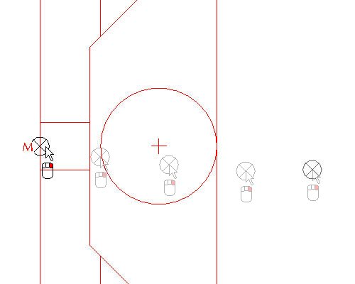
Left click to select the 14 edges highlighted in red in the figure shown below.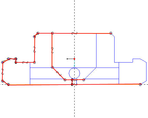
Select Close from the Type dialog.
Click the Dynamic Trim ![]() tool and left click to select the locations shown in the figure below to close the shape.
tool and left click to select the locations shown in the figure below to close the shape.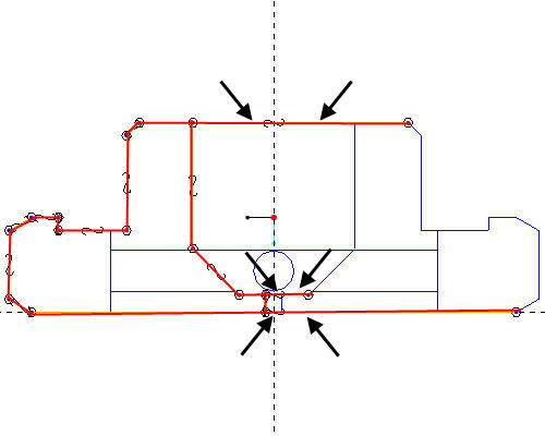
The close shape will appear in the figure below.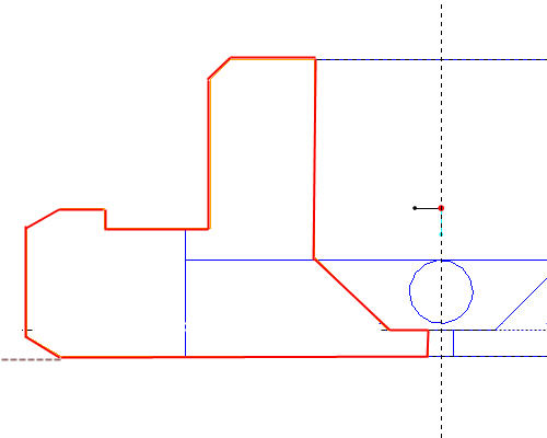
Click Complete Sketch ![]() on the right side toolbar.
on the right side toolbar.
Click CTRL+D to return to the default view.
With the sketch still selected, click the Revolve ![]() tool on the feature toolbar.
tool on the feature toolbar.
|
|
If the sketch is not highlighted in red, select the sketch from the model tree. |
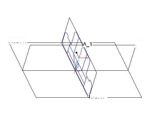
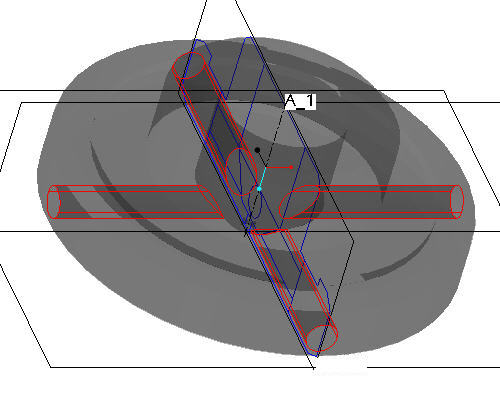
Left click to select the axis A-1 as shown in the figure below.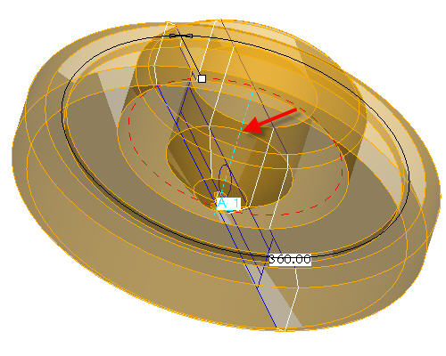
Click the Complete Feature ![]() icon in the dashboard.
icon in the dashboard.
Press CTRL+D on your keyboard to see the default view of your model.
|
|
The opaque, solid geometry will be in the way of seeing the side section, so we'll simply make the solid semi-transparent to ease selection. |
|
|
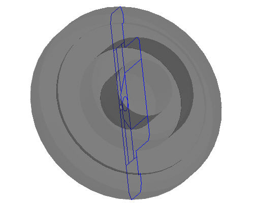
The side view shows a circular hole running radially outward and the front view shows the elliptical intersection of the hole(s) with the conical inner surface of the revolved solid. In this task we'll add a single, radial hole using the imported sketch and then pattern it four times to complete the feature. |
Click the Datum Planes ![]() icon to display the datum planes.
icon to display the datum planes.
Left click on the RIGHT datum plane in the window.
Click the Sketch Tool ![]() icon on the right toolbar to create a sketch.
icon on the right toolbar to create a sketch.
In the Sketch dialog, accept the select references and select Sketch button to close the dialog.
Select the Use Edge ![]() icon from the sketch toolbar. In the Type dialog, select the Single option.
icon from the sketch toolbar. In the Type dialog, select the Single option.
Left click to select the 2 halves of the small sketched circle as shown in the figure below.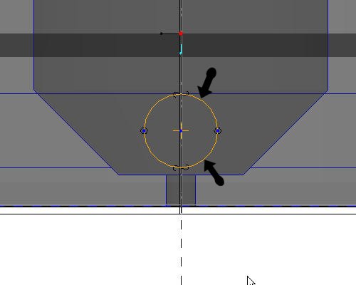
Click Complete Sketch ![]() on the right side toolbar.
on the right side toolbar.
Click CTRL+D to return to the default view.
With the sketch still selected, click the Extrude ![]() tool on the feature toolbar.
tool on the feature toolbar.
|
|
If the sketch is not highlighted in red, select the sketch from the model tree. |
Select Through-all ![]() from the dashboard as the depth direction, and activate the Remove Material
from the dashboard as the depth direction, and activate the Remove Material ![]() icon.
icon.
Select the Complete Feature ![]() button in the dashboard to complete the cut. The part should appear as shown in the figure below.
button in the dashboard to complete the cut. The part should appear as shown in the figure below.
|
|
The single hole has been created and is automatically selected (highlighted in red). By using Pro/ENGINEER's patterning capability, that hole can be replicated in many locations and driven by many different means (dimension, axis, direction, table, etc). Patterning is very powerful in Pro/ENGINEER and we'll simply be touching the surface with this simple axis pattern. |
Click EXTRUDE 1 from the model tree and click the Pattern ![]() tool from the feature toolbar.
tool from the feature toolbar.
|
|
When the Pattern |
In the dashboard, use the pull down to select Axis as the pattern option.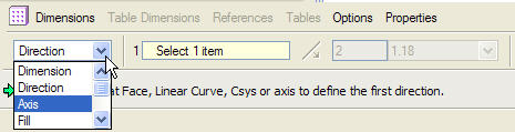
Select the center axis of the part (A_1) to revolve the pattern around.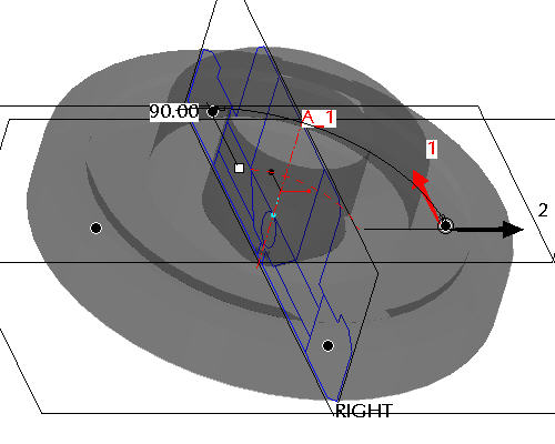
|
|
Make sure that the axes are displayed. If they are not, choose the Datum Axes |
Accept the default increments and angle and click Complete Feature ![]() to see the axial pattern.
to see the axial pattern.
|
|
Create the four slots that ring the part using similar step shown in earlier tasks. Sketch the shape to make solid by a Use Edge |
Right click on FRONT-SECTION from the model tree and select Unhide to display for the next feature.
Right click on SIDE-SECTION from the model tree and select Hide.
Left click on the FRONT datum plane in the window.
Click the Sketch Tool ![]() icon on the right toolbar to create a sketch.
icon on the right toolbar to create a sketch.
In the Sketch dialog, accept the select references and select Sketch button to close the dialog.
Select the Use Edge ![]() icon from the sketch toolbar. In the Type dialog, select the Single option.
icon from the sketch toolbar. In the Type dialog, select the Single option.
Left click to select the 3 lines that make up one of the slots as shown in the figure below.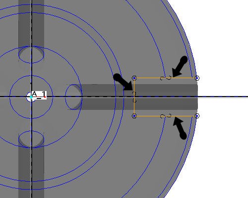
|
|
There is no need to close a cutting sketch if it goes up to or beyond the solid from which it is removing material. Open sketches can also be used when adding material for when the surface the open side touches doesn't run parallel to the extrusion. |
Click Complete Sketch ![]() on the right side toolbar.
on the right side toolbar.
Click CTRL+D to return to the default view.
With the sketch still selected, click the Extrude ![]() tool on the feature toolbar.
tool on the feature toolbar.
|
|
An open section will, by default, assume it is supposed to be a surface feature (not a closed volume). Surface modeling is a powerful capability yet Pro/ENGINEER makes them as easy to use as solids. Surface features are often used to help create solid geometry that might be difficult or impossible to do using only solid features. |
Select Solid ![]() from the dashboard to extrude the sketch as a solid.
from the dashboard to extrude the sketch as a solid.
Select Through-all ![]() from the dashboard as the depth direction, and click Flip Depth Direction
from the dashboard as the depth direction, and click Flip Depth Direction ![]() to change the direction of the extrusion. Activate the Remove Material
to change the direction of the extrusion. Activate the Remove Material ![]() icon. The red boxes in the figure below highlight the icons that should be depressed in the dashboard.
icon. The red boxes in the figure below highlight the icons that should be depressed in the dashboard.

Select the Complete Feature ![]() button in the dashboard to complete the cut. The part should appear as shown in the figure below.
button in the dashboard to complete the cut. The part should appear as shown in the figure below.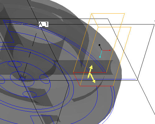
Click EXTRUDE 2 from the model tree and click the Pattern ![]() tool from the feature toolbar.
tool from the feature toolbar.
In the dashboard, use the pull down to select Axis as the pattern option.
Select the center axis of the part (A_1) to revolve the pattern around.
|
|
Make sure that the axes are displayed. If they are not, choose the Datum Axes |
Accept the default increments and angle and click Complete Feature ![]() to see the axial pattern.
to see the axial pattern.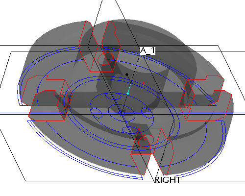
|
|
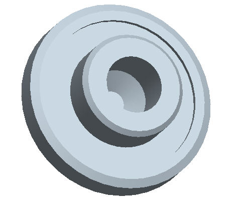
Hide the datum and sketch feature display and change the default gray color to clean up the model. |
Right click on FRONT-SECTION from the model tree and select Hide.
Click View from the pull down at the top of the window and select ![]() Color and Appearance from the drop down menu.
Color and Appearance from the drop down menu.
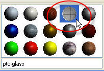
From the Appearance Editor dialog box, select any non-transparent color.
Click Apply from the Assignment section in the dialog box.
Select Close at the bottom of the Appearance Editor dialog box.
Click Datum Planes ![]() , Datum Points
, Datum Points ![]() , Datum Axes
, Datum Axes ![]() and Coordinate Systems
and Coordinate Systems ![]() in the main toolbar to disable their display. The part will appear similar to the figure shown below.
in the main toolbar to disable their display. The part will appear similar to the figure shown below.