Task 8. Add the radial Holes
|
|
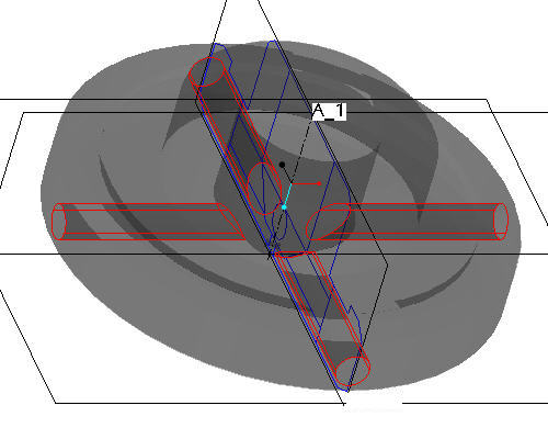
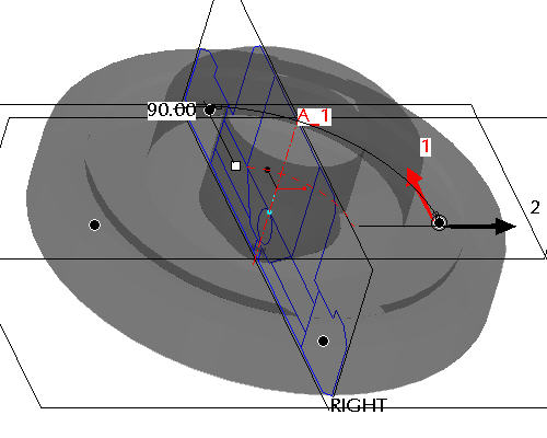
The side view shows a circular hole running radially outward and the front view shows the elliptical intersection of the hole(s) with the conical inner surface of the revolved solid. In this task we'll add a single, radial hole using the imported sketch and then pattern it four times to complete the feature. |
-
Click the Datum Planes
 icon to display the datum planes.
 -
Left click on the RIGHT datum plane in the window.
-
Click the Sketch Tool
 icon on the right toolbar to create a sketch.
 -
In the Sketch dialog, accept the select references and select Sketch button to close the dialog.
-
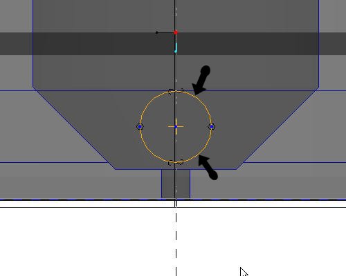
Select the Use Edge
 icon from the sketch toolbar. In the Type dialog, select the Single option.
 -
Left click to select the 2 halves of the small sketched circle as shown in the figure below.
-
Click Complete Sketch
 on the right side toolbar.
 -
Click CTRL+D to return to the default view.
-
With the sketch still selected, click the Extrude
 tool on the feature toolbar.

If the sketch is not highlighted in red, select the sketch from the model tree.
-
Select Through-all
 from the dashboard as the depth direction, and activate the Remove Material
  icon.
icon. -
Select the Complete Feature
 button in the dashboard to complete the cut. The part should appear as shown in the figure below.
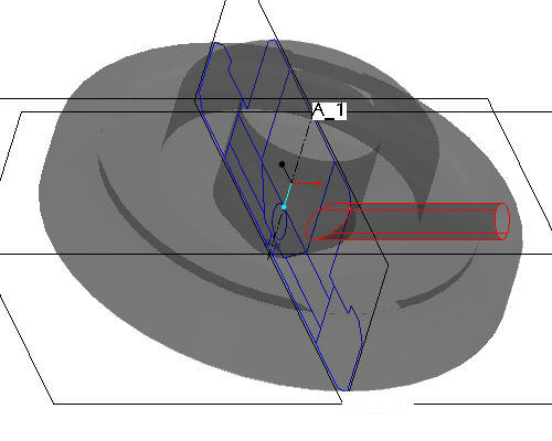

The single hole has been created and is automatically selected (highlighted in red). By using Pro/ENGINEER's patterning capability, that hole can be replicated in many locations and driven by many different means (dimension, axis, direction, table, etc). Patterning is very powerful in Pro/ENGINEER and we'll simply be touching the surface with this simple axis pattern.
-
Click EXTRUDE 1 from the model tree and click the Pattern
 tool from the feature toolbar.
When the Pattern
tool is launched the default pattern option is dimension pattern. Dimension pattern specify incremental changes to the feature dimensions and the number of instances to define the pattern. -
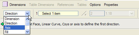
In the dashboard, use the pull down to select Axis as the pattern option.
-
Select the center axis of the part (A_1) to revolve the pattern around.
Make sure that the axes are displayed. If they are not, choose the Datum Axes
 icon.
icon. -
Accept the default increments and angle and click Complete Feature
to see the axial pattern.