Task 9. Create the slot cuts
|
|
Create the four slots that ring the part using similar step shown in earlier tasks. Sketch the shape to make solid by a Use Edge |
-
Right click on FRONT-SECTION from the model tree and select Unhide to display for the next feature.
-
Right click on SIDE-SECTION from the model tree and select Hide.
-
Left click on the FRONT datum plane in the window.
-
Click the Sketch Tool
 icon on the right toolbar to create a sketch.
 -
In the Sketch dialog, accept the select references and select Sketch button to close the dialog.
-
Select the Use Edge
 icon from the sketch toolbar. In the Type dialog, select the Single option.
 -
Left click to select the 3 lines that make up one of the slots as shown in the figure below.
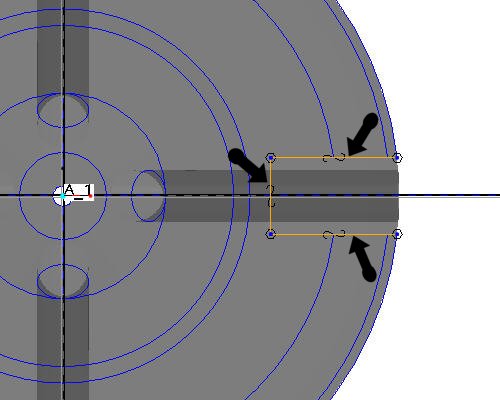

There is no need to close a cutting sketch if it goes up to or beyond the solid from which it is removing material. Open sketches can also be used when adding material for when the surface the open side touches doesn't run parallel to the extrusion.
-
Click Complete Sketch
 on the right side toolbar.
 -
Click CTRL+D to return to the default view.
-
With the sketch still selected, click the Extrude
 tool on the feature toolbar.
An open section will, by default, assume it is supposed to be a surface feature (not a closed volume). Surface modeling is a powerful capability yet Pro/ENGINEER makes them as easy to use as solids. Surface features are often used to help create solid geometry that might be difficult or impossible to do using only solid features.
-
Select Solid
 from the dashboard to extrude the sketch as a solid.
 -
Select Through-all
 from the dashboard as the depth direction, and click Flip Depth Direction
  to change the direction of the extrusion. Activate the Remove Material
  icon. The red boxes in the figure below highlight the icons that should be depressed in the dashboard.

-
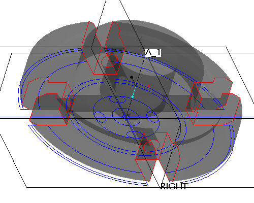
Select the Complete Feature
 button in the dashboard to complete the cut. The part should appear as shown in the figure below.
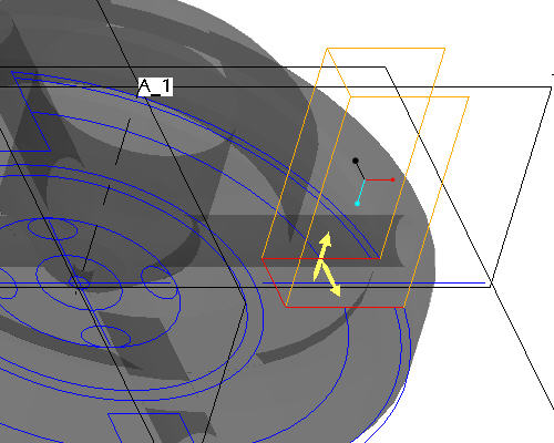
-
Click EXTRUDE 2 from the model tree and click the Pattern
 tool from the feature toolbar.
 -
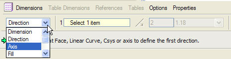
In the dashboard, use the pull down to select Axis as the pattern option.
-
Select the center axis of the part (A_1) to revolve the pattern around.
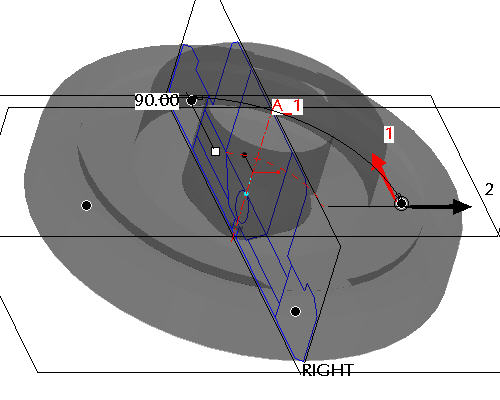

Make sure that the axes are displayed. If they are not, choose the Datum Axes
 icon.
icon. -
Accept the default increments and angle and click Complete Feature
to see the axial pattern.