Task 5. Use the side view of the drawing as the side sketch of the part
|
|
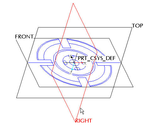
Now that the front view is available, place the side view in an appropriate position on an orthogonal plane. |
-
Left click on the RIGHT datum plane in the window. Note it will turn red when it is selected as shown in the figure below.
-
Click the Sketch Tool
 icon on the right toolbar to create a sketch.

The Sketch Tool allows the user to define a shape using 2-D entities that can be used later to create a sketched feature
-
Accept the default sketching plane and orientation plane and click Sketch from the Sketch dialog in the upper right corner of the screen. This brings you into the sketch tool.
-
Click the Sketch from the pull down across the top of the window and select Data from File and File System...
-
From the File Open dialog box, use the Type drop down list to select Drawing (*.drw).
-
Select SAMPLE.DRW and Open.
-
The previous selected section remains highlighted in red to indicate that it has been selected already. Click Repaint
 in the main toolbar.
 -
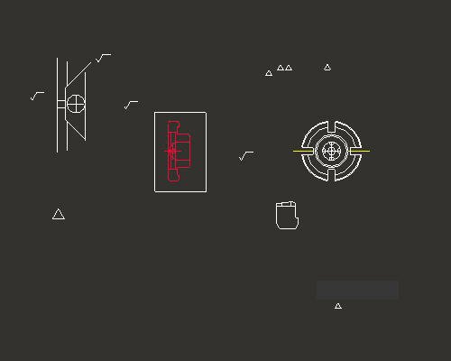
Press and hold the left mouse button and drag a selection box around the drawing view shown in the figure below. Release the left mouse button to close the selection box.
-
From the Select dialog box, select OK.
-
Left click anywhere in the sketching window to place the copied section. The section will appear similar to the figure below.

In the last section you learned how to move the imported sketch using the "X" anchor and saw how it snapped to the datum planes. In this situation however, you would like the point that snaps to the datum planes to be different than its default location. Any of the anchors can be moved around by holding down the right mouse button and dragging them.
-
Click Zoom In
 from the main toolbar and left click to provide a start point to the zoom box around the middle of the pasted sketch and left click to provide an end point to the zoom box. Right click to exit the Zoom command.
 -
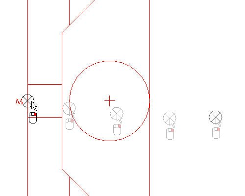
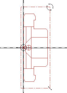
Press and hold Right mouse button and drag the
 anchor to the middle of the left most edge of the section as shown in the figure below.

Only the Right mouse button will relocate the Move anchor. Relocate the Move anchor until a "M" appears. This indicates that the anchor is snapped to the midpoint of the selected edge.
-
Click Sketch Orientation
 icon to see the entire sketch.
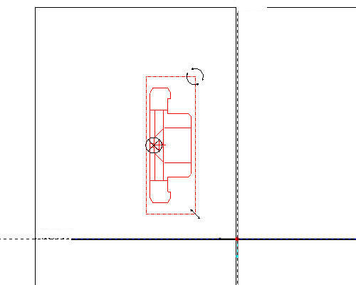
-
In the Scale Rotate dialog box, type 0.25 as the Scale value and 90 as the Rotate value.
The drawing scale was 4:1, therefore we need to scale the copied sketch by 0.25 to get a 1:1 model size.
-
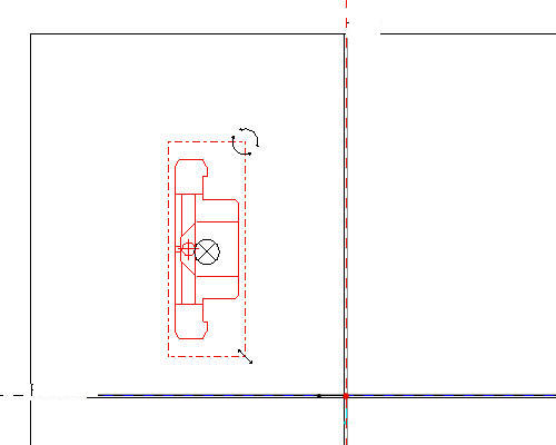
Press and hold left mouse button and drag the X anchor to intersection of the datum planes as shown in the figure below.
-
Click Accept Changes
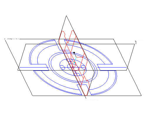
 in the Scale Rotate dialog box. Sketch should appear as shown in the figure below.
The 90 degree rotation of the section orients it correctly with respect to the front section you placed in the previous step. Of course this could also have been accomplished by rotating the sketch plane setup, but for the simplicity of this tutorial it was decided to do that here instead.
-
Click Complete Sketch
 on the right side toolbar.
 -
Click CTRL+D to return to the default view.
-
Right click SKETCH 1 from the model tree and select Rename.
-
Type SIDE-SECTION as the new name. The part should look like the figure shown below.
Renaming the features in the model tree provides for clarity and quick access to select features when needed.