Task 4. Use the front view from the drawing as the front sketch of the part
|
|
Draft entities from drawing views can be imported into a sketch feature in Part Mode. The sketch feature is used to define the shape dimensions and general placement of a sketch-based feature such as a protrusion or cut. |
-
Select Coordinate Systems
 in the main toolbar to disable their display.
 -
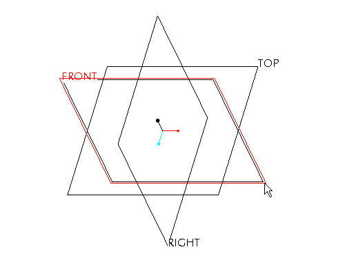
Select the FRONT datum plane from the window.

To select a feature, move the cursor over the feature until it turns blue. Then select the feature using the left mouse button. The selected feature will be highlighted in red.
-
Select the Sketch Tool
 icon on the right toolbar to create a sketch.

The Sketch Tool allows the user to define a shape using 2-D entities that can be used later to create a sketched feature
-
Accept the default sketching plane and orientation plane and select Sketch from the Sketch dialog in the upper right corner of the screen. This brings you into the sketch tool.
-
Select the Sketch from the pull down across the top of the window and select Data from File and File System...
-
From the File Open dialog box, use the Type drop down list to select Drawing (*.drw).
-
Select SAMPLE.DRW and Open.
-
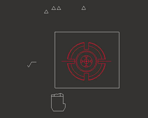
Press and hold the left mouse button and drag a selection box around the drawing view shown in the figure below. Release the left mouse button to close the selection box.
-
From the Select dialog box, select OK.
-
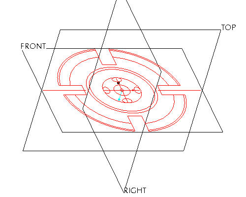
Select anywhere in the sketching window to place the copied section. The section will appear similar to the figure below.
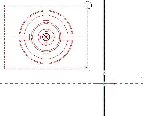

When importing a sketch into the sketcher environment, the scale/rotate preview step allows you to reposition, resize and rotate the entities prior to applying sketcher dimensions. There are three anchors that can be used: The "X" anchor is position, the circular arrows are rotation, and the linear arrows are for scale. Holding down the left mouse button and dragging on any one of these icons will affect the imported entities. In the next section you'll learn how to move the anchors around to change the action points.
-
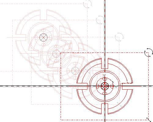
Press and hold left mouse button on the X anchor at the center of the pasted sketch and drag the section to the center of the datum planes. Release the left mouse button when the pasted sketch is in position. Note the anchor should snap to the intersection of the datum planes. Move the pasted sketch as shown in the figure below.
-
In the Scale Rotate dialog box, type 0.25 as the scale.
The drawing scale was 4:1, therefore we need to scale the copied sketch by 0.25 to get a 1:1 model size.
-
Select Accept Changes
 in the Scale Rotate dialog box.
 -
Select Refit
 from the main toolbar to see the imported sketch. Note that the system automatically dimensions the sketch and there are no manual dimensions required.
 -
Select Complete Sketch
 on the right side toolbar.
 -
Select CTRL+D to return to the default view.
-
Right click SKETCH 1 from the model tree and select Rename.
-
Type FRONT-SECTION as the new name.
Renaming the features in the model tree provides for clarity and quick access to select features when needed.
|
|
Toggle Datum Planes |